

With the rise of 5G and other wireless millimeter-wave applications, there has been an increase in front-end antenna solutions that depend on monopole, dipole, and patch antennas. In these devices, the radiation efficiency tends to suffer due to the effect of lossy silicon substrate materials. Enter the dielectric resonator: Antennas using these resonators (made of nonmetallic materials) have a higher radiation efficiency. To increase directivity and gain at high frequencies, engineers can optimize dielectric resonator antenna (DRA) designs with simulation.
From Resonators to 5G: The Evolution of Dielectric Material Applications
In the late 1800s, Lord Rayleigh discovered that a long rod made of a dielectric (i.e., nonconductive) material could act as a waveguide. Scientists continued to study the electromagnetic phenomena surrounding these materials, but there were no practical applications yet.
In 1939, American physicist Robert Richtmyer showed that dielectric rods can also act as resonators. He also proved that this type of resonator radiates because of the boundary conditions at the interface where the dielectric material meets air. Although Richtmyer’s work was significant in the development of DRAs, certain materials necessary to their operation were not readily available until the 1960s.
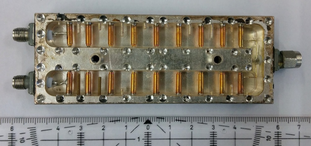
A disassembled RF diplexer at a 5-GHz range with 2 dielectric resonator waveguide filters and 9 transverse resonator stages per filter. Image by wdwd — Own work. Licensed under CC BY-SA 4.0, via Wikimedia Commons.
Later on, DRAs were used as filter element devices in microwave circuits. Starting in the 1980s, they started to get smaller and could operate at higher frequencies, enabling electrical engineers to further develop application areas such as wireless communication.
Today, DRAs are common in satellite and radar systems and are even used in nanophotonics. They also show potential in developing application areas like 5G technology. To improve the performance of DRAs at microwave (and higher) frequencies for future applications, engineers can evaluate designs using the RF Module, an add-on product to the COMSOL Multiphysics® software.
Modeling a DRA Using the RF Module
There are many advantages to DRAs. Not only are they low cost and easy to make, they are also flexible in pattern, bandwidth, feed system, and polarization. In addition, they come in a variety of shapes, including:
- Cylinders
- Rectangles
- Spheres (such as the example below)
- Disks
- Hemispheres
In this example, the dielectric resonator, made of quartz, is a basic radiating element. Passive metallic antenna elements are augmented to increase the antenna directivity and gain. The DRA is excited by a slot-coupled microstrip line. The passive metallic strips enhance the radiation behavior by acting as directors, guiding the radiation pattern and increasing directivity. Here, two strips are placed along the top, with two loops located on each face of the block. The dimensions of these elements are chosen so that they’re resonant at the operating frequency of 2.9 GHz.
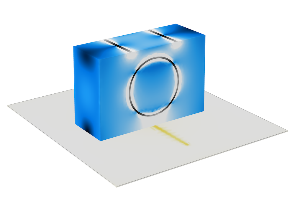
Slot-coupled DRA model.
The power source for the antenna is represented at the lumped port, which is fed via a microstrip line from the port. The microstrip line extends beyond the slot and forms a tuning stub and, along with the ground plane, is treated as being infinitely thin and a perfect electrical conductor (PEC). Surrounding the resonator is a sphere with the properties of a vacuum, with a perfectly matched layer (PML) acting as a boundary to free space.
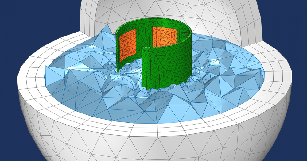
As for meshing, it’s best to stick to at least five elements per wavelength in each material, and curved edges and surfaces with at least two elements per 90° chord. A swept mesh is suitable for the PML areas, and you can use tetrahedral elements of unit aspect ratio for the other modeling regions. The mesh is automatically configured through the physics-controlled mesh.
Examining the Simulation Results
After solving the structure for an operating frequency of 2.9 GHz, you can study the far-field radiation patterns generated by the DRA. You can visualize these patterns on the E-plane and H-plane (left plot below) as well as in 3D (right plot below). The results from the simulations indicate that the resonator and metallic strips help increase the directivity of the antenna.


Left: Far-field radiation pattern on the E-plane (blue) and H-plane (green) at 2.9 GHz. Right: 3D far-field radiation pattern.
As this example demonstrates, you can evaluate the dielectric resonator’s effect at different frequencies for an antenna as well as optimize a DRA design to improve the directivity and gain.
Next Steps
To get started with modeling DRAs, click the button below. Doing so will take you to the Application Gallery, where you can log into your COMSOL Access account and download the MPH-file and step-by-step instructions for the example.
Further Reading
- Learn about designing spiral slot antennas on the blog
- Find out how you can use modeling to gain insight into a radome’s ability to improve antenna directivity


Comments (0)