Analyze the Electrodynamics of a Magnetic Power Switch via Simulation

Have you ever plugged one too many devices into an electrical circuit? This can overload the circuit and damage its components. To avoid this issue, many homes have devices like electric switch circuit breakers to interrupt the current when a critical current is reached. Other types of circuit breakers are used to prevent issues in high-voltage situations, like citywide power lines. In this blog post, we discuss using simulation to study a class of heavy-duty circuit breakers: magnetic power switches.
Circuit Breakers Increase the Safety of Electrical Systems
In residential buildings, power is often distributed between various electrical circuits connected to a panel. If too many devices draw power from a single electrical circuit, it can exceed the circuit’s limit, causing an overload. Other electrical events, like overcurrents, can also harm critical parts of the system, requiring expensive repairs and possibly creating a fire hazard.
Circuit breakers and fuses help prevent these issues. Let’s focus on electric switch circuit breakers, which “trip” and interrupt the current flow by moving a plunger as soon as a defect is detected. Unlike fuses, circuit breakers do not need to be replaced after activation; they can simply be reset. As anyone who has used both options knows, resetting a circuit breaker is much easier.
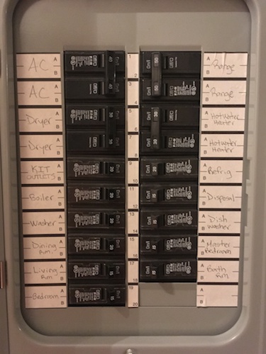
A circuit breaker panel.
Circuit breakers are classified by features such as:
- Construction type
- Voltage rating
- Structure
- Interruption methods
So far, we’ve only described circuit breakers for household use. Breakers based on very different designs are used to protect systems with higher currents than you would deal with on a residential scale, such as power lines and factories. Here, we analyze one of these more heavy-duty types of circuit breakers, a magnetic power switch type of circuit breaker. This electromechanical device uses the magnetic attraction from a current flowing through coils to move iron plungers. The switch resets to its initial state when the driving current is turned off.
Accurately Simulating a Magnetic Power Switch with the AC/DC Module
The tutorial model of the magnetic power switch has two main purposes:
- Determining possible solutions to modeling a magnetic power switch
- Investigating the working principles of the switch
The model geometry can be created using the built-in CAD tools in the COMSOL Multiphysics® software as well as parameterized Geometry Parts to more finely control the geometry. You can also use symmetry to reduce the geometry to 1/4 of its original size, and embed the model in an air domain to compute the electromagnetic fields.
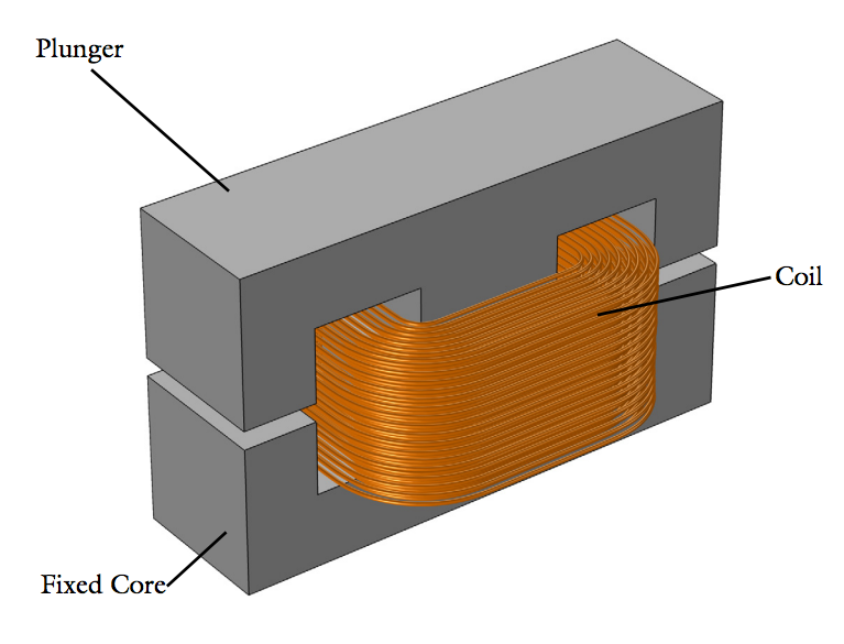
The magnetic power switch geometry.
The geometry consists of two bulk E-shaped iron cores that are separated by an air gap. The lower E-core is fixed, while the upper E-core, also called the moving plunger, is held in place by a prestressed string. As a current flows through the copper coil on the central leg of the lower E-core, it exerts an attractive force onto the plunger. You simulate the attractive force with a Force Calculation feature and use the resulting value in an ordinary differential equation (ODE) describing the plunger dynamics based on Newtonian mechanics.
Eventually, the force reaches a threshold value, causing the plunger to close the air gap by moving down toward the lower E-core. The closing time depends on the spring stiffness. As such, the model takes into account the spring and constraint arrangements that keep the plunger at an equilibrium position.
You can model the closure by coupling the Magnetic Fields interface to the Moving Mesh interface. Together, these interfaces calculate the magnetic fields in a geometry that changes over time.
Magnetic power switch model in motion.
In the model, you can simulate the movement and time it takes for the plunger to close the air gap and account for the influence of magnetic forces and induced currents.
Next, let’s discuss the rigid body dynamics of the magnetic power switch.
Transient Analysis of a Circuit Breaker Device
The main time-dependent study step, which analyzes a time period from t = 0 s to t = 1 s, can be broken into different stages. The current grows in the first 45 ms of the simulation. During this time, the air gap remains open, since the electromagnetic attractive force isn’t enough to overcome the force of the opposing spring. It isn’t until 45–85 ms after the start of the simulation that the electromagnetic attractive force becomes enough to move the plunger down toward the iron core.
While this movement occurs, the current begins to decrease because of the inductance changing. The inductance reaches its minimum value when the plunger has closed the air gap and stopped at its new position. Then, since the contact between the plunger and core creates a new stationary RL circuit, the current increases again. The slope of this increase is dependent on the new characteristic time of the device.


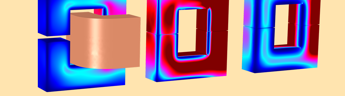
Magnetic flux density norm results showing an open air gap at t = 0.05 s (left) and a closed air gap at t = 0.1 s (right). The induced eddy currents seen here appear to screen the interior of the core from the magnetic field. You resolve the currents in these plots by using a boundary layer mesh and restricting them to a region as large as the skin depth.
The simulation results show the evolution of both current density and magnetic flux density over time. As seen below, the spring reaches its maximum compression at t = 0.1 s (bottom left). Note that the induced currents in the core decay by t = 0.5 s (bottom right), well before the simulation time ends.
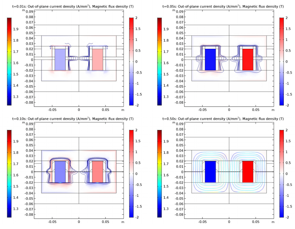
Plots showing the current density (surface) and magnetic flux density (streamlines) of the magnetic power switch. The plots are used for studying instances when the spring is prestressed (top left), begins to compress (top right), reaches a maximum compression (bottom left), and is completely compressed with the induced currents in the core decayed (bottom right).
You can also analyze the core losses caused by the induced current activity in the switch. This is useful to investigate potential overheating in the switch, which is a key concern in circuit breaker design.
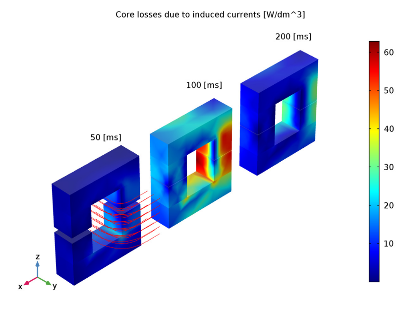
Core losses caused by induced currents at 50, 100, and 200 ms.
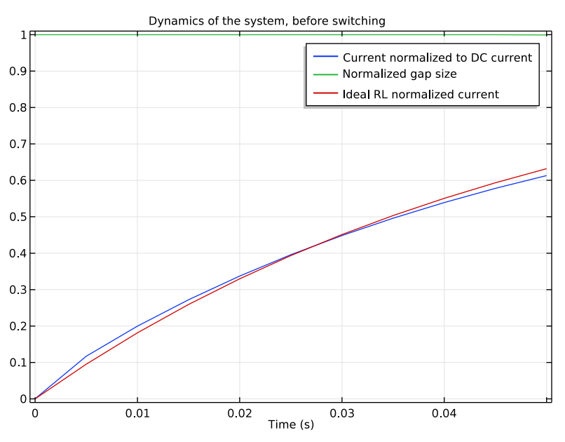
Moving on, the 1D plots can be used to study the dynamics of the switch during the process. Start by looking at the beginning of the simulation, before switching (plunger movement). At this time, the spring isn’t compressed and the gap size remains the same (as indicated by the straight green line). Here, you can see that the normalized current (blue line) is similar to the response of the ideal system (red line).
Plot showing the magnetic flux density norm before the plunger motion.
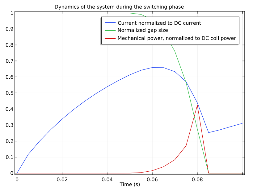
By expanding the time scale, you can look at the dynamics of the system during and after the plunger moves. The plot below indicates that the mechanical power (red line) only rises above zero when the plunger is in motion, as expected. When the gap closes, the mechanical power returns to zero.
Plot showing the magnetic flux density norm during plunger motion.
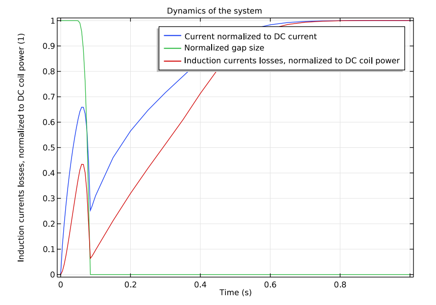
Take a look at the induction losses in the core (the red line in the graph below) over a longer time period. These losses are significant when the plunger is in motion — a factor that may need to be considered when designing magnetic power switches, depending on the device details and its intended performance. When the movement ceases, the normalized current increases again. This is expected for a nonlinear RL circuit.
Plot showing the magnetic flux density norm throughout the entire simulation time.
Simulation can be a helpful tool when studying circuit breakers such as magnetic power switches. Using models like the one discussed here, you can study key magnetic power switch design factors. Give the tutorial model a try yourself for more information on this process.


Comments (2)
Philip Swan
August 14, 2019The materials talk about the problem statement and the results, but skip the most important part, which is how to actually use Comsol to do the this project. Please just redo the whole project from scratch while recording with screen capture utility (try hard to avoid using pre-built components or skipping steps for the sake of brevity – that is super annoying), and please post the resulting video. Thanks!
Gennadii Liziakin
March 11, 2024In the model library there is two approach to build this model. First one is with ODE and second one is with multibody feature. Could you explain why do we need multibody feature in instead ODE? I ask it because multibody module you need to buy separately from AC/DC module.