

In this blog post, we discuss the general process for how to set up electrochemistry and battery models from scratch. For demonstration purposes, we will use a lemon battery as our example.
Introduction to the Lemon Battery Problem
A classical laboratory exercise in school chemistry is the lemon battery. By the use of a lemon, a piece of copper (a penny or some copper wiring), and a piece of zinc (such as a galvanized nail), it is possible to build a battery that can power a small electrical device in a matter of a few minutes. As many have noticed, however, the applicability of these batteries is notoriously limited, delivering powers in the sub mW range.
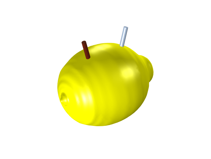
A lemon with two electrodes (left: copper; right: zinc).
Modeling Objectives
The first question a modeler should pose is: What is the goal of the modeling project? This might seem trivial, but by spending some extra thought on this question, you can often save a lot of time.
For this example, we will address the following question: What limits the power output of a lemon battery over time, and how can it be improved?
In other words, we want to use the model as a design tool to boost the wattage above the 1 mW level. Other common modeling objectives could be to reduce the volume, weight, and/or cost.
The power output is directly related to the voltage and current at the electrode terminals. This means that our model needs to include the major sources of voltages and voltage losses in the battery, and assessing the current means that the transport of charge (ions and electrons) needs to be included in some way as well. The word time in the question above is also essential, since this means we need to include transients.
What measures can we take to improve the power? This is sometimes hard to know initially, but considering the very materials (lemon, copper, and zinc) to be design constraints, a likely assumption is that our only way of boosting performance will be by altering the geometrical configuration (placement) of the electrodes.
In conclusion: We need to define a time- and space-dependent model.
Chemical Species and Reactions
Now, let’s discuss what chemical species and reactions to include in our model.
Inspecting the nutritional information of lemons reveals that the electrolyte consists of citric acid (300 mM = 0.3 moles per liter) and ascorbic acid (3 mM), both being weak acids buffering to a pH of approximately 2 (which corresponds to a proton concentration of 10 mM). There is also a mix of additional ions, the most prominent cations being potassium (35 mM) and calcium (7 mM). There are also some trace amounts of zinc (9 μM) and copper (6 μM) ions already present in the lemon before introducing our electrodes. In addition to this, there is a bunch of anions (such as chloride) present to match the cations, since the bulk of electrolytes are always charge neutral.
Given that the two electrodes consist of Cu(s) and Zn(s) metals, respectively, and that these may dissolve, the following electrode reactions seem reasonable to consider for further analysis:
Here, and in the following, the stated equilibrium potentials, Eeq, have been calculated for the specified concentrations from our nutritional information using the Nernst equation. We are also using double-directed arrows for all reactions at this point, indicating that the reactions are fully reversible, and may proceed in any direction.
Since the electrolyte is aqueous, there are protons and hydroxide ions present due to water autoprotolysis occurring homogeneously throughout the lemon pulp:
However, due to the acidic pH, we consider the hydroxide concentration to be negligible.
In aqueous systems, metal hydroxides may be formed. However, consulting the Pourbaix diagrams for Zn and Cu reveals that for our low pH, these are not likely to form in the lemon.
That the system is aqueous also means that, depending on the electrode potentials, both oxygen and hydrogen may be either formed or consumed on the electrodes:
These two reactions may occur on both electrodes, although here we generally assume faster kinetics on the copper electrode.
The potassium and calcium that we found in the nutrition list have standard dissolution potentials way lower than that of both zinc and copper, implying that they do not deposit on any electrode to any large extent. Similarly, chlorine gas evolution has a standard potential higher than that of oxygen and should hence also be possible to neglect for now.
The presence of multiple different metal ions in combination with the mixed electrode potentials results in a rather complex system of possible metal deposition side reactions, in particular on the Zn electrode. For instance, trace amounts of Cu ions, or any other nobler metal ions in the lemon may deposit on the Zn electrode. This may alter the electrocatalytic properties of this electrode, for instance, deposited Cu may increase the activity for hydrogen evolution significantly. We choose to also ignore these effects at this point and assume metal copper and zinc deposition dissolution to occur on their respective electrodes only.
Regarding the weak acids (citric and ascorbic acids), these molecules are relatively large and complex, which typically results in slow kinetics. We simply assume them not to react on the electrodes. We also neglect the forming of complexes of the weak acids with the metal cations. As for the other species on the nutrition list (sugars, fat, etc.), we neglect them too for now.
Electrolyte Transport
We now turn our attention to the transport processes in the electrolyte.
First, we need to decide on a model for the electrolyte charge transport and the electrolyte potential, since the potential difference between electrolyte potential and the electric potential in the metals is a major driving force for the electrode reactions.
We concluded above that there are significant amounts of ions present (K+, Cl–, etc.) that do not participate in the electrode reactions. This allows for a supporting electrolyte assumption, which means that the conductivity of the electrolyte is not assumed to change significantly as a result of the electrode reactions. We can hence assume a constant conductivity (0.35 S/m) and solve for the electrolyte potential using a partial differential equation version of Ohm’s law.
The electrode reactions above include Cu2+, Zn2+, H+, H2, and O2, so the concentrations (chemical activities) of these species need to be defined in some way in the model.
Zn(s) and Cu(s) are assigned the constant chemical activity 1 and need no further treatment. We also assume that the shapes of the electrodes are not altered as a result of metal dissolution.
Since the ion concentrations are low in comparison to that of pure water (55.5 M), we can assume the electrolyte to be diluted. This means that we assume that species in the electrolyte only interact with water molecules, acting as a solvent.
Using the dilute assumption, the transport of Zn2+ and Cu2+ can be defined using the Nernst–Planck equations, where we need only to provide one diffusivity/mobility parameter per ion.
Due to the presence of the weak acids (citric and ascorbic acid), with pH buffering capabilities that do not participate in the electrode reactions, we assume a constant pH (hydrogen concentration).
Gases in the air surrounding the outer surface of the lemon (nitrogen, oxygen, carbon dioxide, etc.) may dissolve and diffuse into the electrolyte. Here, we treat all gases except oxygen as inert. Oxygen is assumed to be in equilibrium with the surrounding air at the outer lemon surface. From the surface, it may diffuse toward the electrodes, where it is reduced. The oxygen diffusion process may also be described by the Nernst–Planck equations (which equals Fick’s law of diffusion for uncharged species). Since the oxygen reduction reaction has the highest equilibrium potential of our reactions in our chemical system, we should not have to consider oxygen gas evolution.
The transport of hydrogen is a bit more problematic to model. The hydrogen evolution/oxidation reaction has an equilibrium potential located in the middle of our reacting system, meaning that the reaction may proceed in any direction (depending on the local electrode potential). If hydrogen gas bubbles are formed on the electrodes, this poses modeling complications, since this introduces a second phase in our system (in addition to the liquid phase). Two-phase systems are generally complicated to model, and for the lemon pulp, there is no straightforward way for how to describe the gas bubble transport. We therefore chose to simplify this by assuming that all hydrogen is formed as gas with activity 1, and that any formed gas is immediately vented off before it gets a chance to get oxidized. Equation-wise, this is achieved by only allowing the hydrogen reaction to proceed irreversibly as a reduction reaction (hydrogen evolution). For positive (oxidation/anodic) electrode overpotentials, the reaction rate is set to 0. In this way, the hydrogen concentration need not be solved for by the model.
System Boundaries and Choice of Geometry
When it comes to the pieces of zinc and copper, these metals have very high conductivities in relation to that of the lemon pulp, so it suffices to model the electric (electronic) potential of the metals as boundary conditions. As a result of this, and the above discussion, the proposed battery model is completely governed by what goes on in the electrolyte (the pulp of the lemon) and the reactions on the electrode surfaces. We hence select the outer surface of the lemon, excluding the metal domains, as system boundaries.
Also, when constructing the model geometry, we consider symmetry by slicing the lemon in half to save computational resources.
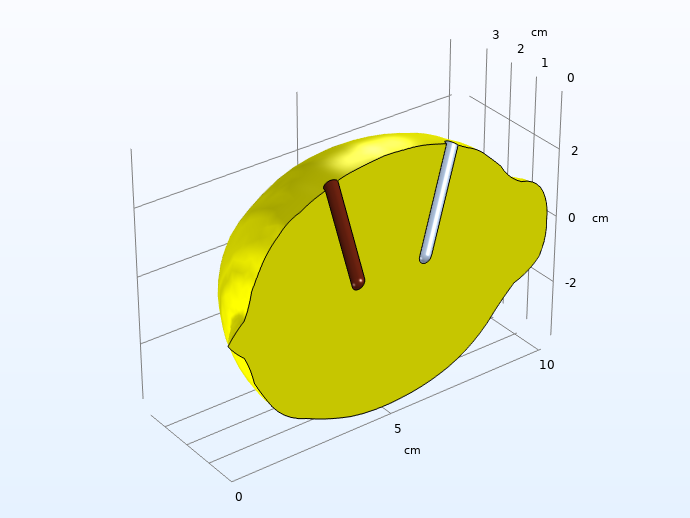
Computational domain after considering symmetry and high conductivity in the electrodes.
Note: It is always recommended to use the lowest possible dimension, since this usually saves model development and computational times. For the actual lemon, you could possibly consider a 2D geometry with axial symmetry around a central axis, but since we want full freedom to place the electrodes, we have to construct the model in 3D. Even for our case, however, it would still be recommended to start the modeling project in lower dimensions just to test the different domain equations and boundary conditions and to make sure they converge. This model would, for instance, be suitable to model in 1D first, emulating two planar electrodes with an electrolyte in between, but we have omitted this step in this blog post.
Simulating a Lemon Battery in COMSOL Multiphysics®
In the results shown below, we use the Tertiary Current Distribution, Supporting Electrolyte interface in COMSOL Multiphysics to model the lemon battery. We define charge transport by a constant conductivity, species transport by the Nernst–Planck equations, electrode reactions based on built-in mass-action law Butler–Volmer kinetics, and Nernst-equation-based calculation of the equilibrium potentials.
A word of caution here: Most parameter values, particularly for the electrode kinetics, are assessed for sole demonstration purposes and are not based on literature.
In the simulation, the used load cycle consists of a 1 min rest from initial conditions (the nutrition list values), followed by a 1 min load at 0.5 mA, and a 1 min rest.
Explaining the Voltage Curve During Operation
The figure below shows the resulting voltage and current from the simulation.
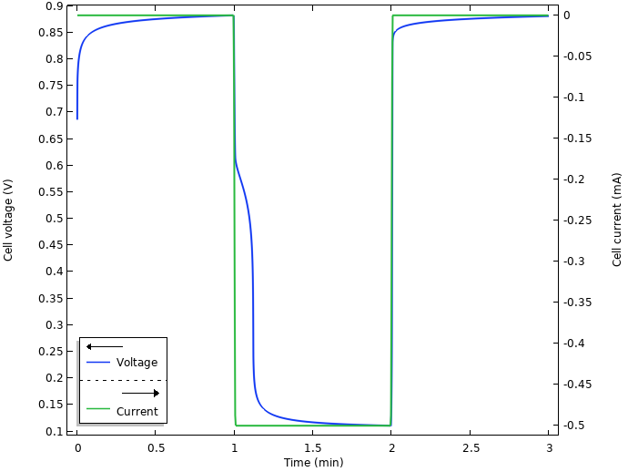
Voltage and current.
Initially, when the electrodes are inserted into the lemon, there seems to be some kind of relaxation occurring, with a slowly increasing cell voltage toward 0.9 V. When the current is turned on at t = 1 min, there is a swift substantial drop from the open circuit voltage to an operational voltage of about 0.1 V. We also note some kind of relaxation after the current is shut off after 2 min.
By multiplying the cell voltage with the current, we can also plot the power output of the cell.
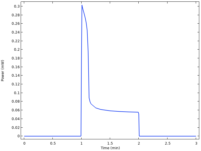
Power output from the cell.
There is power loss from 0.3 to 0.06 mW only a few seconds after the load is turned on, related to the substantial voltage drop.
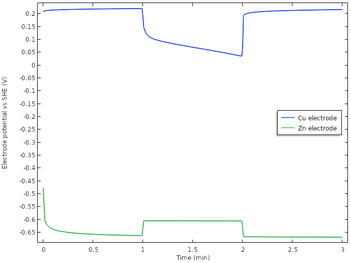
What is behind this enormous (for an electrochemist) approximately 0.75 V drop in cell voltage when the current is turned on? We begin our analysis by plotting the operating electrode potentials (vs. SHE) at the tip of the two electrodes versus time:
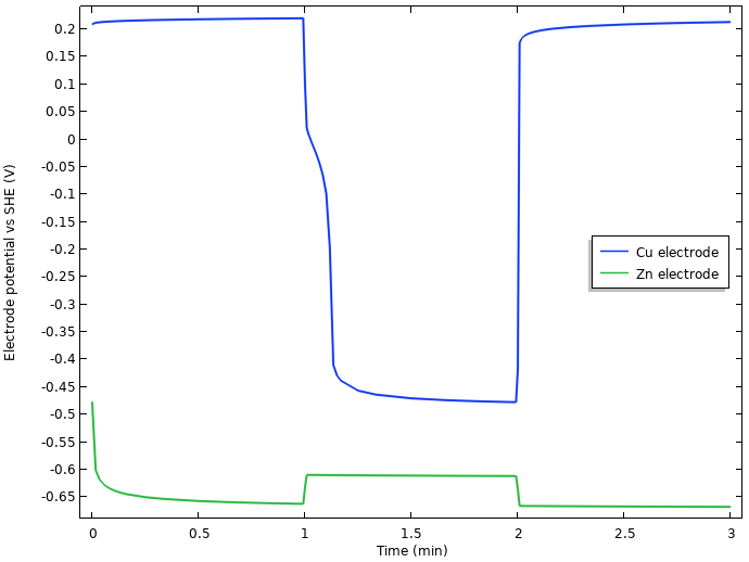
Electrode potentials vs. SHE at the tip of the nails.
We note that the initial increase of cell voltage at rest seems to be related to something occurring at the negative zinc electrode, but that most of the 0.75 V drop in cell voltage when the current load is turned on seems to stem from the positive copper electrode.
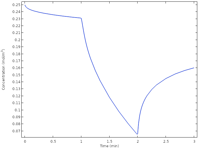
Plotting the average oxygen concentration at the copper nail surface vs. time in the next figure hints to the explanation.
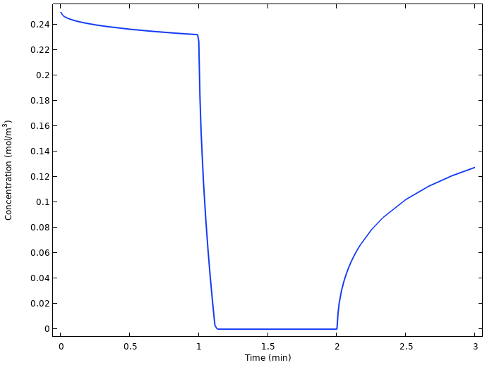
Average oxygen concentration at the copper electrode.
The oxygen concentration at the copper electrode drops to zero quickly as the current is turned on, and starts relaxing back to a higher value as soon as the current is turned off again. The reason is that the slow diffusion of oxygen from the lemon surface to the copper electrode is not enough to sustain the battery current once the load is turned on. Another way of formulating this is that we are operating the battery above the limiting current for oxygen reduction.
Plotting the integrated local current densities of the different electrode reactions for the whole copper nail surface offers further insights.
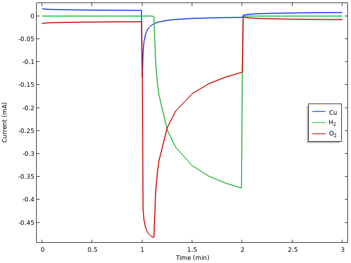
Integrated local current densities at the positive electrode.
If we closely inspect the currents during the initial rest period in the above figure, we can see that copper dissolves (a small positive current) at the same rate as the oxygen reduces (a small negative current). This indicates that there is continuous copper corrosion occurring during rest. Hydrogen evolution is not present during the initial rest. This is due to the equilibrium potential for hydrogen evolution being lower than the resulting mixed electrode potential, which attains a value between the equilibrium potentials for copper dissolution and oxygen reduction. (If hydrogen gas had been present at the electrode, however, this would have been oxidized, but as we mentioned above, hydrogen gas is not assumed to be present in the lemon at any time.)
When the current is turned on, we see an initial surge in the oxygen reduction current that then falls back as oxygen gets depleted. Since all currents are constrained to sum up to the 0.5 mA battery load due to the way we operate the battery, the potential drops when the electrode runs out of oxygen until it reaches an electrode potential below that of hydrogen evolution, which then can step in to provide the required reduction current. Due to the water autoprotolysis reaction and the high water concentration, there is a vast supply of protons at the electrode, with a limiting current for hydrogen evolution orders of magnitude higher than that of oxygen reduction. We also note that copper starts to get deposited when the potential of the electrode drops during load.
We hence have a transition from an electrode potential governed by copper dissolution-oxygen reduction at rest, toward a hydrogen-evolution-governed electrode for prolonged loads. The large drop from the rest potential of about 0.2 V vs. SHE to the operational potential of about -0.45 V vs. SHE during load can be explained by the significantly lower equilibrium potential for hydrogen evolution than for oxygen reduction. Kinetics also plays some part in the resulting values, but we leave that out of our analysis for now.
Self-Discharge at the Negative Electrode and Battery Capacity
The following figure shows the integrated local current densities of the individual electrode reactions at the negative electrode.

Integrated local current densities at the negative electrode.
Here, both oxygen reduction and hydrogen evolution result in zinc dissolution at rest. (The initial relaxation phenomena is related to the interplay between all of these reactions, but we will not be discussing it further here.)
During the load period, the zinc dissolution increases to match the 0.5 mA cell current, plus the oxygen reduction and hydrogen evolution currents.
The continuous zinc dissolution indicates that it is the initial mass of zinc metal we put into the lemon that will determine the capacity of the battery, since at the positive electrode, the water autoprotolysis reaction will provide us with an almost infinite source of protons for the hydrogen evolution reaction. The exact number of amp hours we can discharge from the battery will however depend on the interplay between the load and the self-discharge reactions.
Assessing the Voltage Losses
During load, we have three major possible sources of voltage losses in our model:
- The ohmic drop in the electrolyte
- The activation overpotential for driving the zinc dissolution on the negative electrode
- The activation overpotential for driving the hydrogen evolution reaction (or oxygen reduction) on the positive electrode
First, we plot the ohmic drop in the electrolyte, 30 seconds into the load pulse.
Electrolyte ohmic drop (mV), 30 seconds into the charge pulse.
A 40 mV voltage drop is significant, but not huge.
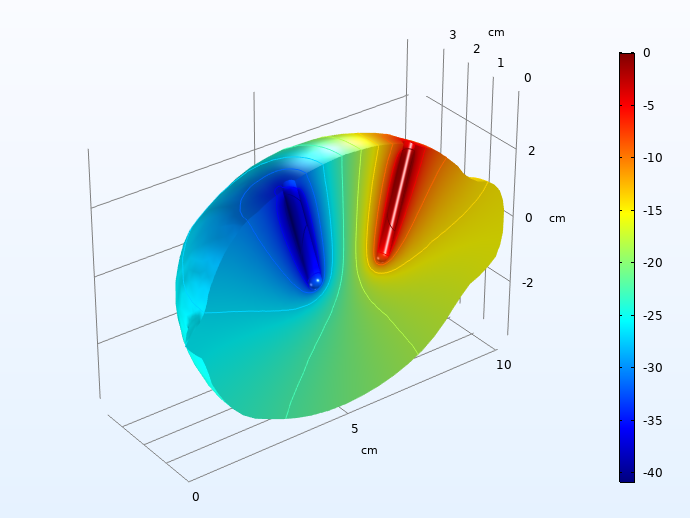
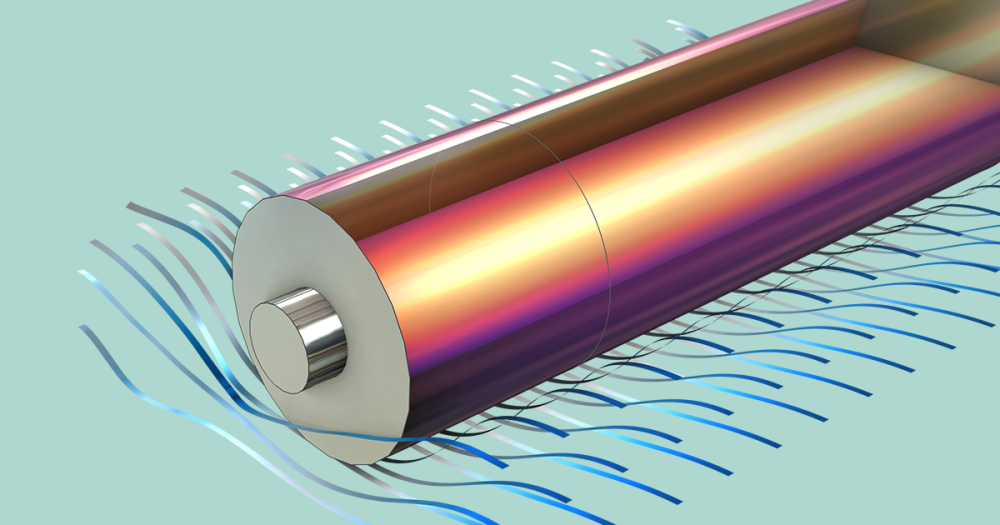
Next, we plot the local overpotentials for the Zn dissolution on the negative electrode, and the hydrogen evolution on the positive electrode.
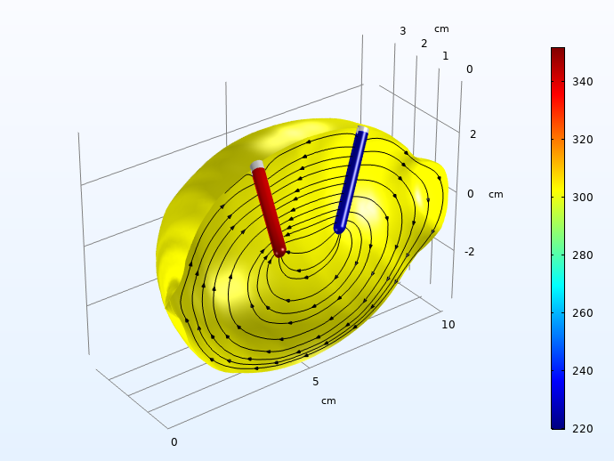
Hydrogen (left) and zinc dissolution (right) activation overpotentials (mV, absolute values), 30 seconds into the charge pulse. The streamlines depict the electrolyte currents along the symmetry plane.
The activation overpotentials on the two electrodes sum up to about 0.5 V 30 seconds into the load pulse. These are way higher than the ohmic losses for charge transport in the electrolyte.
Boosting Power Output
Now we return to our original modeling project goals to see if we can improve the power output from the battery.
Improving the intrinsic electrode kinetics, which on the Zn electrode and for our set of parameter values contribute the most to cell polarization, is hard to achieve without altering the very electrodes or electrolyte. However, catalytic activity may also be improved by increasing the amount of available electrode-electrolyte interface area. The reason for this is that all current has to pass over the electrode-electrolyte interfaces on each electrode, and the voltage loss associated with an electrode reaction gets higher the higher the local current density. By increasing the available area for the electrode reaction, the local current density per electrode area thus gets reduced, and in turn also the associated voltage loss.
Since we have a large volume of space available within the lemon, a larger geometric area of the electrodes (or simply more nails) should be a viable way to improve performance. This would, however, also increase self-discharge, since this is also directly related to the active electrode area.
Cell performance would also benefit slightly if the ohmic drop in the electrolyte could be reduced. A way of achieving this would be to simply place the electrodes closer to each other. We would have to proceed with caution, however, since we could increase the effect of unwanted Cu deposition on the Zn electrode — something that could possibly worsen the Zn electrode kinetics. We have, however, not yet included such effects in the model.
The holy grail would be if the 0.5 V voltage boost (see the figure above) from using oxygen reduction instead of hydrogen evolution on the copper electrode could be exploited in some way. A way to achieve this could be to place the copper electrode closer to the lemon surface in order to shorten the diffusion distance for oxygen.
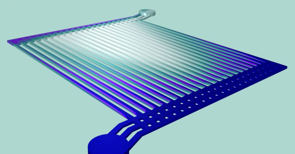
Based on our modeling results, we now propose the following power-optimized design for the lemon battery.
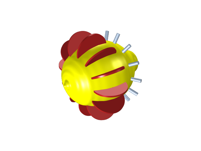
Power-optimized lemon battery design.
In this design, we have exchanged the copper nails for pennies. We also introduce multiple electrodes (one couple for each wedge of the lemon, 12 couples in total). It should perhaps be noted that the wiring work for the new design will require some quite agile fingers.
Introducing multiple metal electrodes increases the overall electrode surface area; something that should allow us to run the cell at a higher total current (in principle, we are now running 12 batteries in parallel). Introducing copper pennies instead of nails increases the electrode area further, but more importantly, this should also increase the amount of copper electrode surface located closer to the lemon surface, which should allow for higher limiting currents for oxygen reduction.
When we run a new simulation for the new design, for a total current of 6 mA (0.5 mA per wedge), we get the following result for the cell voltage:
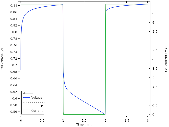
Voltage and current for the new design.
The corresponding cell power reveals that we are now able to operate the cell well above the 1 mW level:
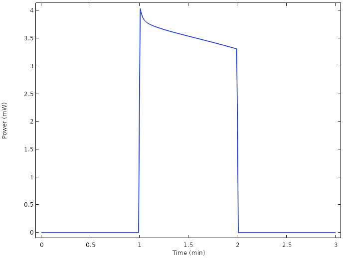
Power for the new design.
A major contributor is the use of multiple electrodes, but plotting the electrode potentials reveals that we have managed to increase the potential positive electrode potential during load more than 0.5 V.
Electrode potentials vs. SHE at the tip of the electrodes for the new design.
Examining the oxygen concentration once more at the copper electrodes reveals that we now do not reach full depletion of oxygen at the electrode at any time.
Average oxygen concentration at the copper electrodes for the new design.
Correspondingly, a plot of the positive electrode reaction currents shows that the main electrode reaction during load now is the oxygen reduction reaction.

However, the oxygen concentration and current is continuously dropping over time. A way to achieve further improvements could be to introduce hydrophobic porous gas diffusion media to promote transport of oxygen between the surface of the lemon and the copper electrodes. Since gas phase diffusion generally is about four to five orders of magnitude faster than for liquids, this would increase the transport of oxygen significantly. The details for how this should be done would be very suitable to explore with a model. Possibly, we would also have to exchange our copper metal to something more active for oxygen reduction, such at platinum. However, platinum pennies tend to be hard to come by.
A lemon battery functioning in this way has, however, already been invented, albeit for alkaline electrolytes. It is called a zinc-air battery.
Next Step
Interested in other examples of electrochemical modeling? Explore more electrochemistry models in the Application Gallery by clicking the button below.


Comments (8)
Srihari Gangaraj
May 20, 2020Very interesting post and entertaining during the WFH days. Thanks for sharing.
Priyanshu Vishnoi
February 24, 2021In this model, you have neglected the hydrogen gas bubble formation. What if there is an electrochemical model in which hydrogen concentration from the hydrogen evolution reaction is so high that bubbling will certainly take place? Is there any way to incorporate hydrogen bubble formation (and transport) in electrochemical models using tertiary current distribution, Nernst-Plank physics?
Henrik Ekström
February 24, 2021 COMSOL EmployeeYes, the currents are extremely low, so hydrogen bubble formation is indeed neglected in this model.
For an example of bubble formation and transport due to gas evolution in combination with the Tertiary Current Distribution, Nernst-Planck interface, please check out https://www.comsol.com/model/two-phase-flow-modeling-of-copper-electrowinning-using-bubbly-flow-75111
Hunter Strathman
October 14, 2021Would it be possible to share your model from this tutorial? I’m struggling to simulate multiple redox reactions at an electrode and this would be very helpful.
Henrik Ekström
October 15, 2021 COMSOL EmployeeHi Hunter.
The model can now be downloaded from https://www.comsol.com/model/lemon-battery-86411
Hunter Strathman
October 15, 2021Thanks! I think the link to the .mph is incorrect. When I click it, I’m redirected to comsol.com with no option to save the .mph file.
Henrik Ekström
October 18, 2021 COMSOL EmployeeDoesn’t clicking the “Download application files” tab work? I just tested it on a computer external to comsol, and it works there.
Hunter Strathman
October 18, 2021Yes, it’s working today. Not sure what the issue was before. Thanks!