
When designing electromagnetic coils, we may want to adjust the position of the coils to achieve a desired magnetic field strength within a particular region of space. This is possible to do within the COMSOL Multiphysics® software by using the add-on AC/DC Module and Optimization Module to combine parameter and shape optimization. Let’s find out how.
The Initial Coil Design and Optimization Problem
Let’s suppose that we are tasked with designing a coil such that the magnetic field along part of the centerline is as close to a target value as possible. As we saw in an earlier blog post, we can achieve this by adjusting the current through each turn of the coil to be different. However, this requires that we include a separate current control for each turn in our physical design. Instead, we can use a single current control for the entire coil and adjust the physical spacing of the coils along the axial direction.
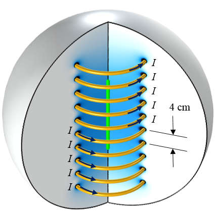
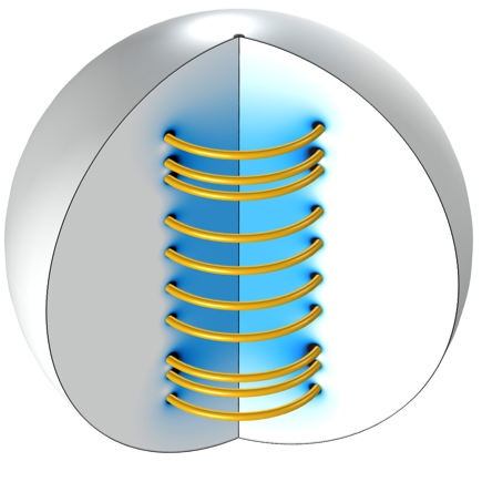
A ten-turn axisymmetric coil. The objective is to alter the magnetic field at the centerline (green).
The case that we will consider here is shown in the image above. A ten-turn axisymmetric coil is driven by a single current source; that is, the same current flows through each turn. The initial coil design spaces the 1-cm-diameter coil turns a distance of S0 = 4 cm apart. Since the coil is axisymmetric (and we are only interested in solutions that are symmetric about the z = 0 plane), we can use the reduced computational domain shown in the schematic below.
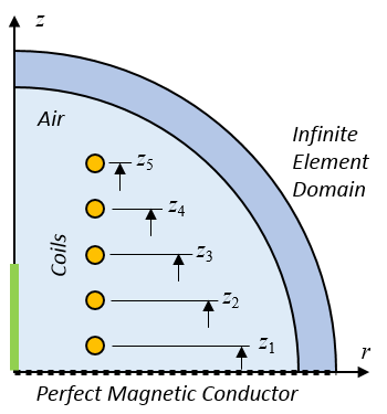
The computational model. We want to change the five coil positions and the coil current.
Our optimization objective is to get the Bz field as close as possible to a desired value, B0, along a portion of the centerline by changing the coil current and z-location of the five coils. Each coil can move \pm \Delta Z_{max} and there must be a gap of G0 between the adjacent coils, so the first coil offset has a different lower bound. We also need to include a constraint on the peak current as well as constrain the current to be greater than zero. Although physically speaking, it isn’t necessary to constrain the current to be greater than zero, it’s a good optimization modeling practice to do so, since this keeps the constrained design space small.
More formally, these statements can be written as:
& \underset{I, \Delta Z_1, \ldots ,\Delta Z_5}{\text{minimize:}}
& & \frac{1}{L_0} \int_0^{L_0} \left( \frac{B_z}{B_0} -1 \right) ^2 d l \\
& \text{subject to:}
& & -(S_0-G_0)/2 \le \Delta Z_1 \leq \Delta Z_{max}\\
& & & -\Delta Z_{max} \leq \Delta Z_2, \ldots ,\Delta Z_5 \leq \Delta Z_{max}\\
& & & G_0 \le (Z_5-Z_4) \\
& & & G_0 \le (Z_4-Z_3) \\
& & & G_0 \le (Z_3-Z_2) \\
& & & G_0 \le (Z_2-Z_1) \\
& & & 0 \leq I \leq I_{max}\\
\end{aligned}
We solve this problem with a combination of parameter and shape optimization by using the Optimization and Deformed Geometry interfaces in COMSOL Multiphysics.
Setting Up and Solving the Optimization Problem in COMSOL Multiphysics®
We can begin our implementation by reviewing the model developed here, which optimizes for a particular field value. We start with the same Optimization interface and Integral Objective feature introduced in the previous blog post. Two Global Control Variable features are then used. The first sets up the displacements of the five coils, using Control Variables Scaling to scale the optimization variables close to unity. The second Global Control Variables feature similarly defines and constrains the current.
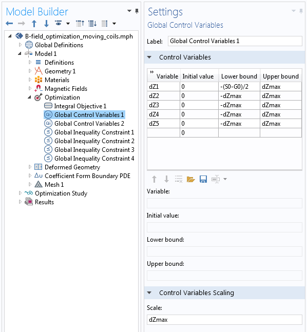
The definitions of the variables that control the five coils’ positions.
The five Control Variables shown in the screenshot above define the displacements of the coils, as well as a small square region of space around each coil, which is shown as the green domains in the illustration below. As these green domains move up and down, the surrounding yellow domains must stretch and shrink to accommodate, while the surrounding blue domain is fixed. Since we know the displacements of the green domains, we can specify a linear variation of displacement along all of the red edges. This linear displacement variation is computed using a Coefficient Form Boundary PDE interface, as described in an earlier blog post on modeling translational motion.
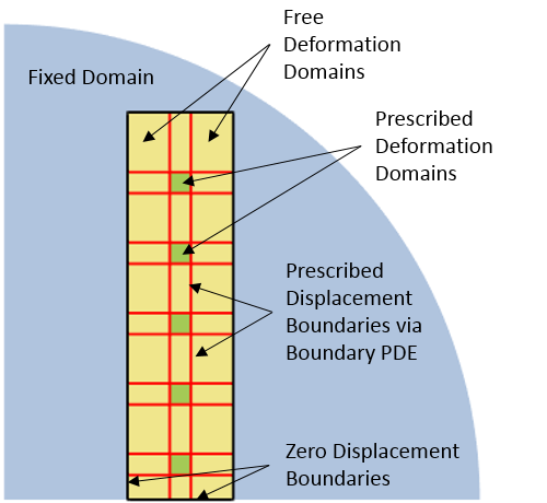
The definitions of the deformations for the various domains in the model.
This information about the specified displacements of the various domains is set up using the Deformed Geometry interface, as shown in the screenshot below. The Prescribed Deformation domain features move the green domains and the yellow domains are allowed to deform due to the Free Deformation domains. The Prescribed Mesh Displacement boundary features apply to the black and red edges and completely define the deformations of the yellow domains.
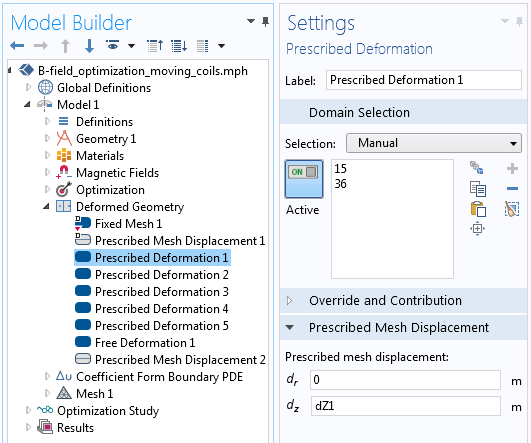
The control over the coil turn displacement via the Prescribed Deformation feature in the Deformed Geometry interface.
As a consequence of setting up the Deformed Geometry interface in this way, the five control variables for the positions of the coils now represent a shape optimization problem. Previously, we have discussed shape optimization in a more general case from structural mechanics. Shape optimization takes advantage of the ability of COMSOL Multiphysics to compute design sensitivities with respect to changes in the shape of the geometry.
We also need to define a set of Global Inequality Constraints to prevent the green domains surrounding the coils from getting too close to each other and intersecting. The screenshot below shows this implementation. Note that the constraint is scaled with respect to the gap size G0 so that the constraint equation is also close to one in magnitude.
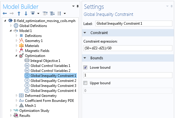
One of the four constraints that keep the coils from getting too close to each other.
Due to the large deformations that can occur in the domains around the coils that stretch and contract, it is also helpful to use a mapped mesh.
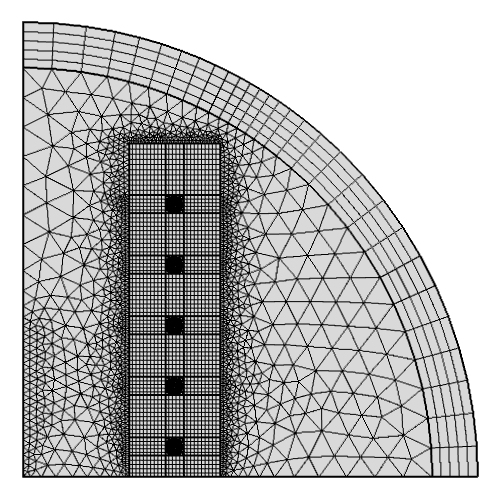
A mapped mesh is used in the deforming domains around the coils. The infinite element domain also has a mapped mesh.
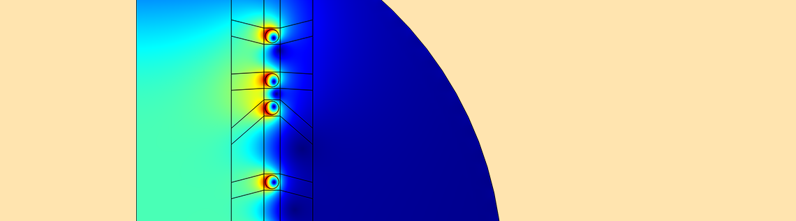
We can then solve this problem using a gradient-based optimization solver (SNOPT), taking advantage of the analytically computed gradients. The current through the coil and the coil positions are adjusted to minimize the above objective function. The results of the optimization are shown in the figure below.
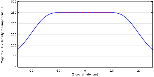
The magnetic flux density’s z-component along the centerline for the optimized coil.
The optimized coil positions.
Concluding Thoughts on Optimizing the Spacing of Electromagnetic Coils
We have introduced a model that uses a combination of shape and parameter optimization to adjust the coil current and spacing between the coils in a 2D axisymmetric coil. By taking advantage of the Optimization and Deformed Geometry interfaces, we are able to analytically compute the derivatives for this problem and converge to an optimum very quickly.
Further Resources
- Read a blog post on modeling a linear electromagnetic plunger
- Browse the Optimization category on the COMSOL Blog

Comments (9)
Ivar Kjelberg
April 25, 2017Hei Walter
Thanks for a very nice demo of coil optimisation, simple (with COMSOL) and efficient 🙂
AKASH ORAON
May 30, 2017In the present example,if it is desirable to change the radius/diameter of coil wire,
how it can be done ?
Walter Frei
May 30, 2017Hello Akash, Please note that the Global Parameters define a number of parameters, including wire and coil radius, and you can adjust these if you would like.
AKASH ORAON
May 31, 2017Yes Walter, ‘Global Definitions Parameters’ includes r0, and this can be changed once for geometry.
I was trying to vary wire radius/diameter also with Global control variables (optimization), like current in this example.
How this can be done ?
Walter Frei
May 31, 2017Hello Akash, Yes, you can also make the radial positions of the wires design parameters in your optimization. Such modifications are left as a simple additional exercise for the user.
AKASH ORAON
May 31, 2017Hi Walter, thank you for the answer. Yes, I had tried for changes of radial position dR(of coil), similar to dZ.
My doubt here remains for the wire cross section diameter/radius(r0), how this can be taken as optimization variable ?
(wire cross section here lies inside prescribed deformation).
Walter Frei
June 21, 2017Hello Akash,
You would follow the same basic procedure of the using the deformed geometry to change the radius/diameter.
Jiefu Cen
May 16, 2019Hi Walter,
Thanks a lot for this nice and clear demo of optimization with deformed geometry. I have been trying to do the same in 3D but I think I encounter a problem in convergence/solver settings.
I define Fixed Domains, Free Deformation, Prescribed Deformation and Prescribed Movement Boundary just like above.
Also, following your blog post “Model Translational Motion with the Deformed Mesh Interfaces”, I define Coefficient Form Boundary PDE on the deformed faces and Coefficient Form Edge PDE on the deformed edges.
Due to symmetry, I also cut all domains and the coils half using Magnetic Insulation boundary (with Ground potential in Magnetic and Electric Field interface).
The default solver setting is Segregated Solver and the convergence of my model gets stuck in the second iteration. Do you see any problems in my model?
Any help is really appreciated.
Jeff
瓜 瓜
October 27, 2019请问我想改变电流和单饼线圈之间的间距来优化,使之在I/Ic时候达到最大储能量,Ic和某点磁场有关,但是我不知道怎样定义ic