LiveLink™ for Solid Edge® Updates
For users of LiveLink™ for Solid Edge®, COMSOL Multiphysics® version 5.5 brings user-defined selections and synchronized material properties. Read more about these features below.
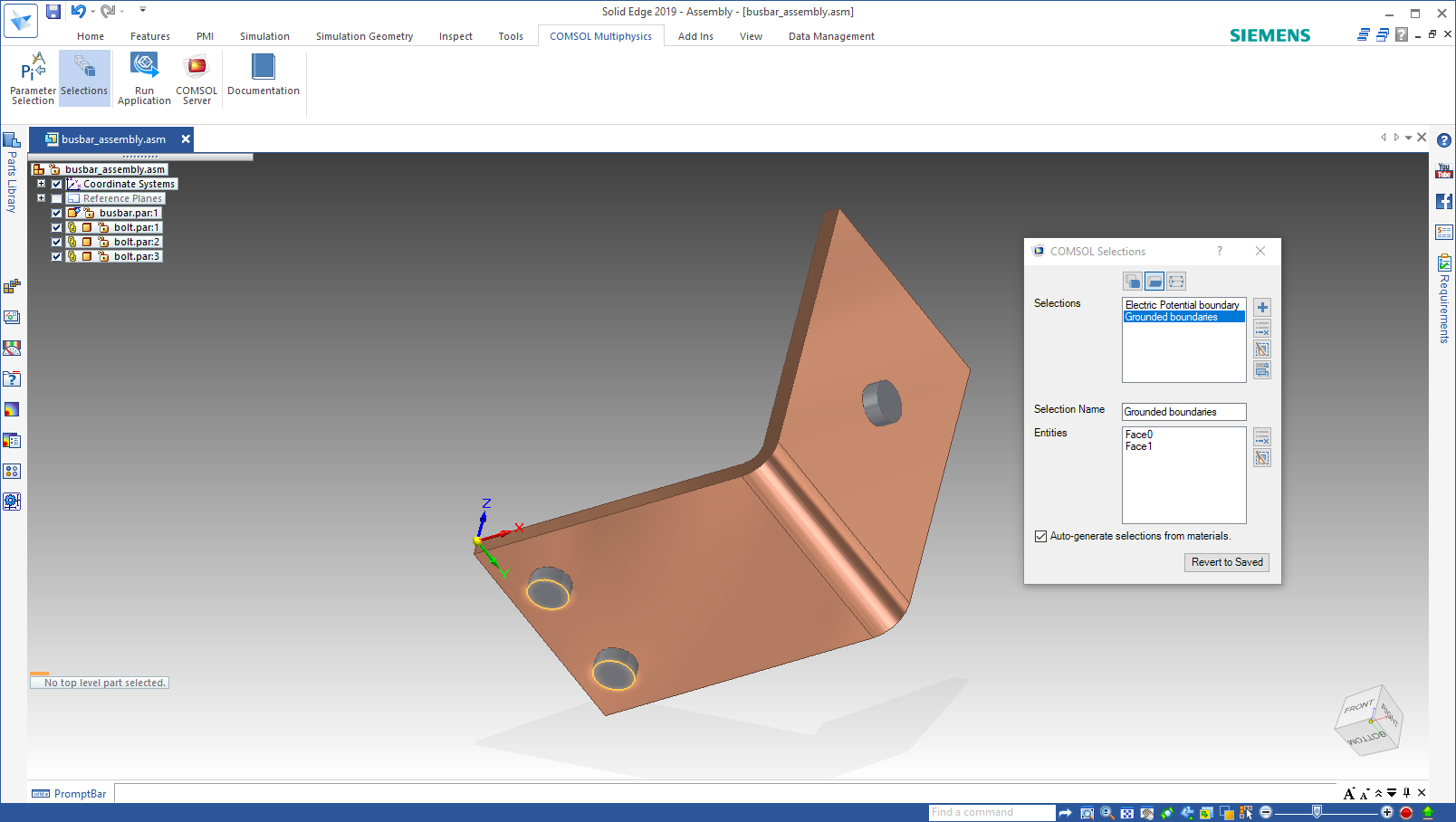
User-Defined Selections
Expanding on the functionality that synchronizes selections based on material assignments in the CAD model in Solid Edge®, the LiveLink™ interface now adds support for user-defined selections. In the newly added COMSOL Selections interface in Solid Edge®, you can define selections that are synchronized with the COMSOL Multiphysics® model. You can choose to synchronize selections for assembly features, bodies, faces, or points, which become selections in the model when the CAD design is synchronized with COMSOL Multiphysics®.
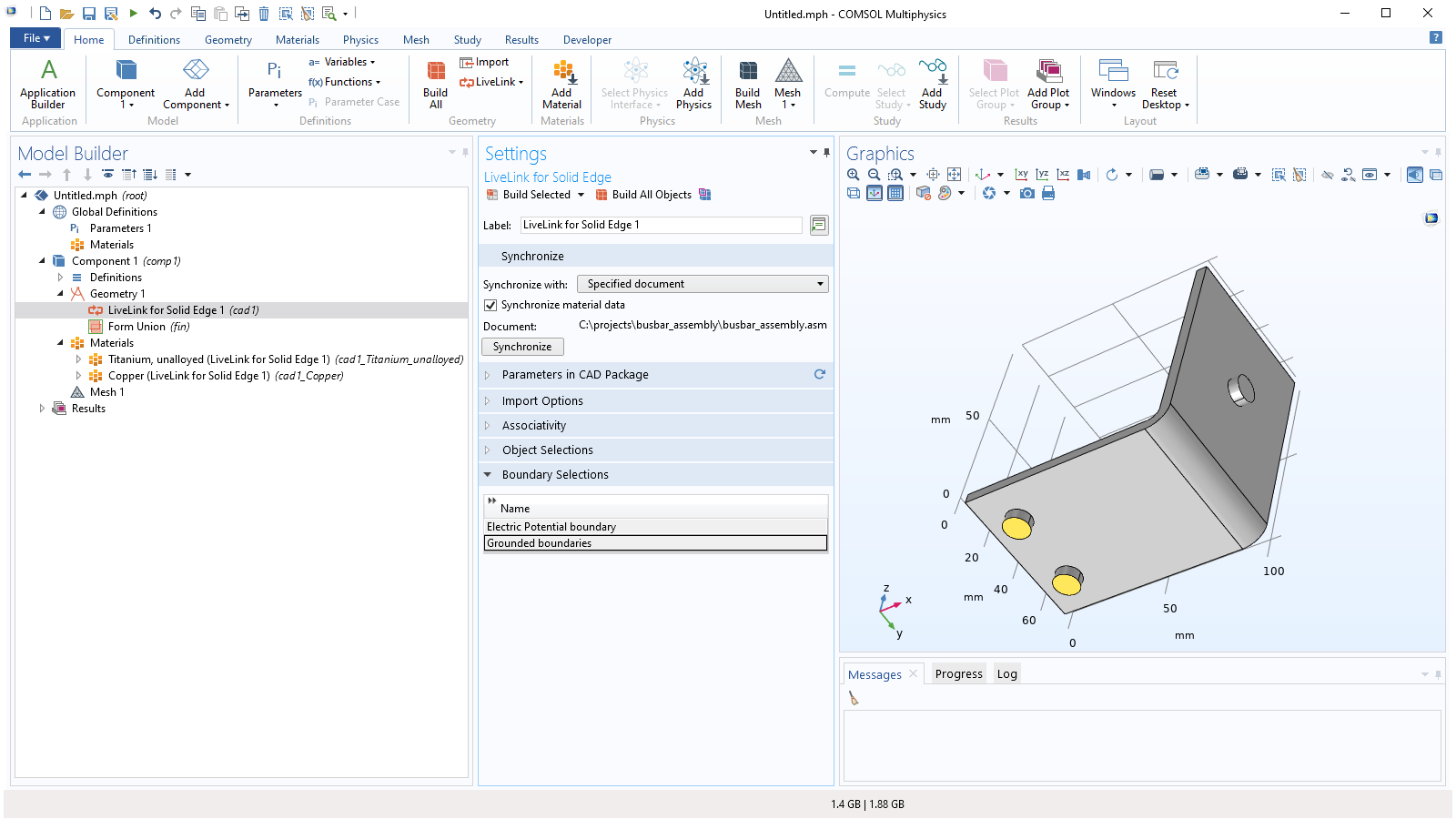
Support for Synchronizing Material Properties
For users of LiveLink™ for Solid Edge®, COMSOL Multiphysics® version 5.5 supports the synchronization of material properties applied in Solid Edge®. Based on the material data, Materials nodes are created in the component of the LiveLink™ feature, and their selection is set to the corresponding material in Solid Edge®. The synchronization of materials is enabled with a Synchronize material data check box in the Synchronize section of the LiveLink for Solid Edge node.

Associative Geometry Import
The CAD file import functionality now supports associative geometry import to retain physics and other settings on the geometry after the file is reimported due to an updated design. The import reads information in the CAD files to identify the geometric entities in the file. This information is usually available when importing CAD files saved in the native format of the software where it was created.
Selections from Materials, Layers, and Colors
The CAD file import functionality now generates selections based on the material and layer assignments of the geometric objects, when available in the CAD file. Selections are also generated for colors assigned to geometric entities. The selections are listed in the Settings window of the Import feature.
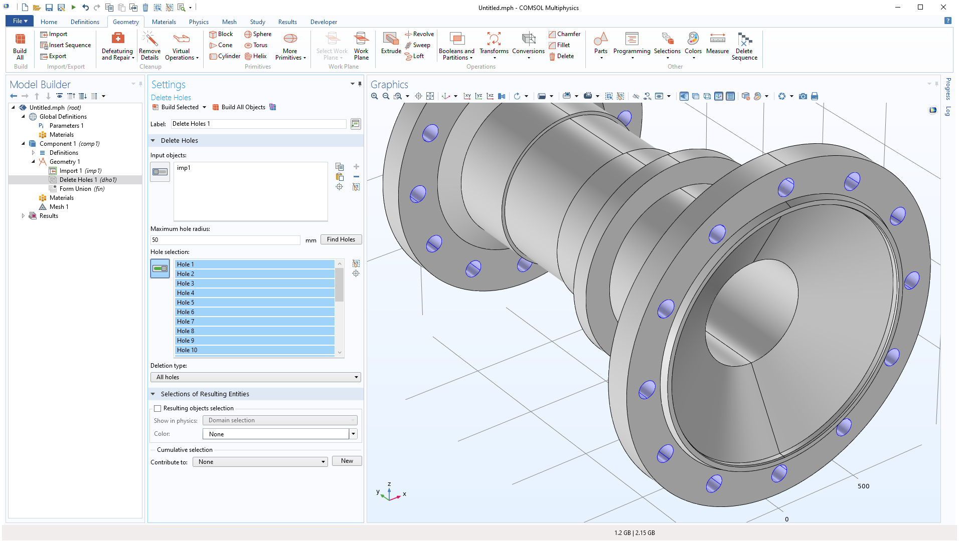
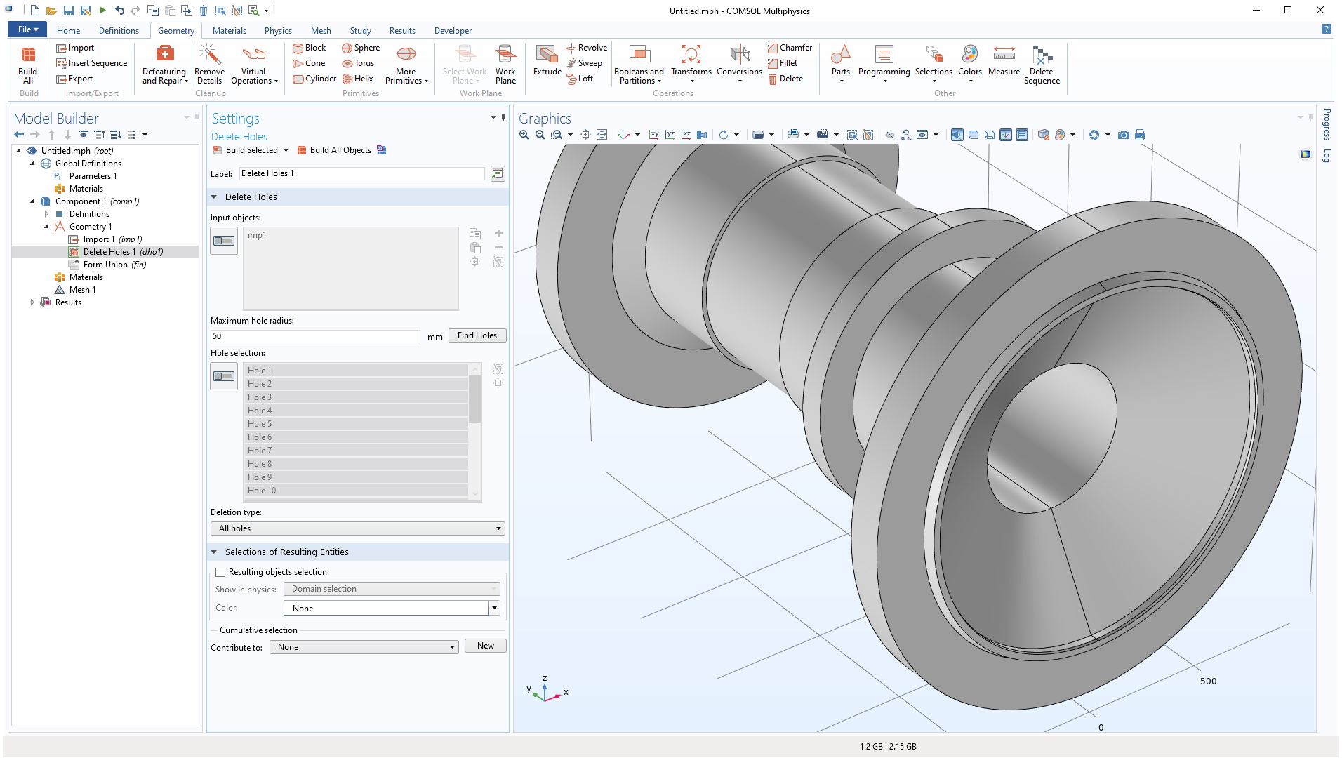
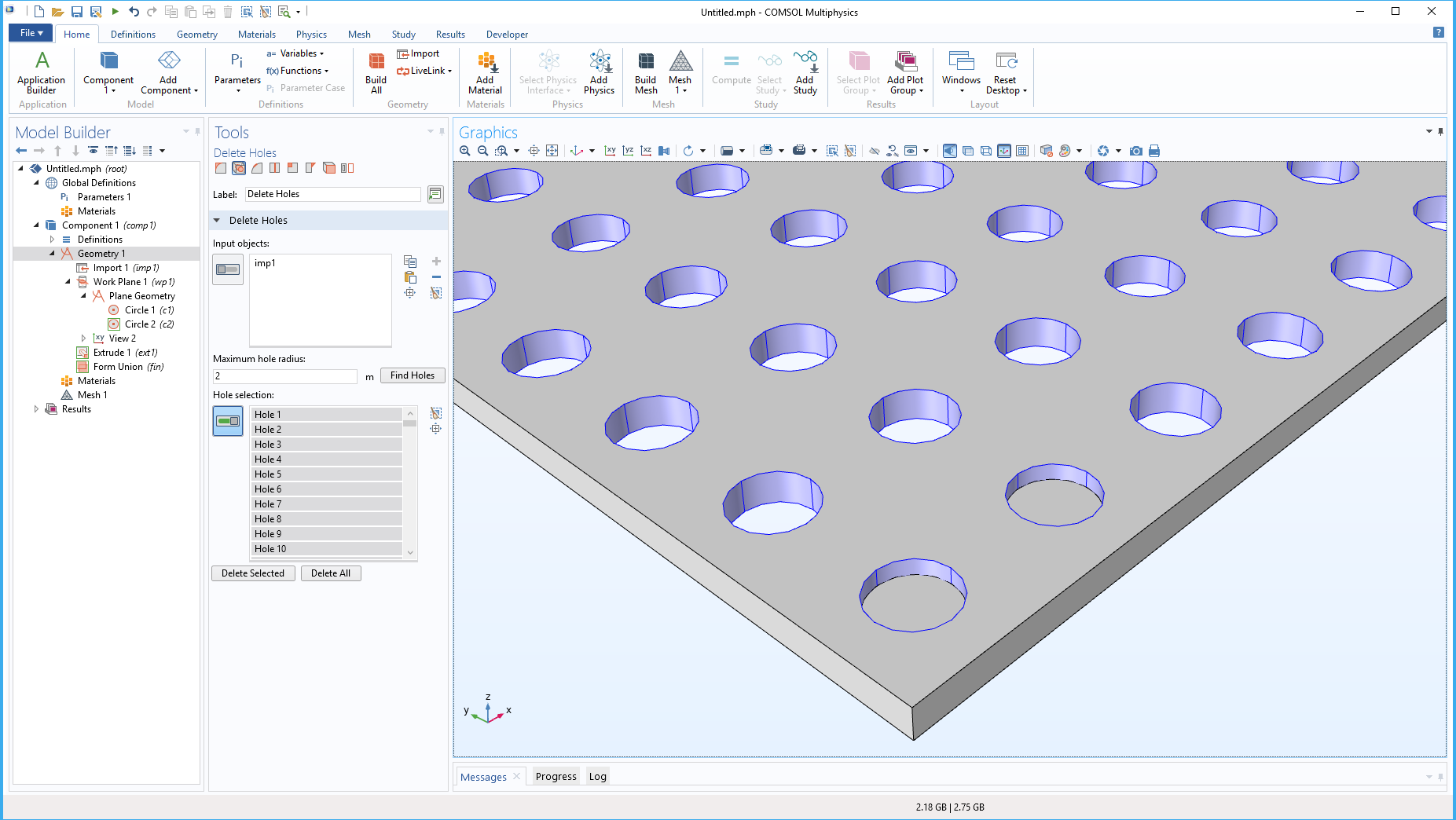
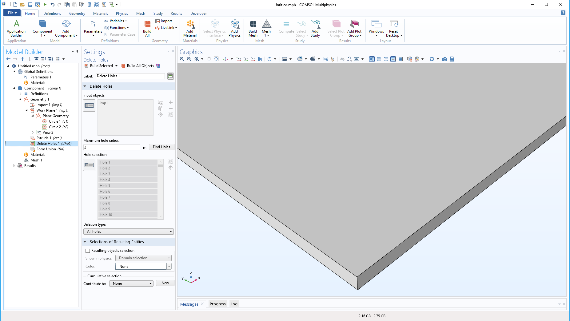
Delete Holes Defeaturing Operation
A new defeaturing operation called Delete Holes finds and deletes cylindrical holes whose radii are smaller than a given number that you can specify. After specifying a maximum radius, a Find Holes button will automatically add the appropriate holes to the selection list.
Support for New and Updated CAD File Format Versions
The CAD file export functionality now supports writing 3D geometry to the following file formats:
- IGES (.igs, .iges): 5.3
- STEP (.step): AP203
The CAD file import and export functionality has been extended to support new versions for the following file formats:
Read from File
- ACIS® (.sat, .sab, .asat, .asab): 2019 1.0
- NX™ (.prt): 1847
- Parasolid® (.x_t, .xmt_txt, .x_b, .xmt_bin): V32.0
- PTC Creo Parametric™ (.prt, .asm): 6.0
- SOLIDWORKS® (.sldprt, .sldasm): 2019
Write to File
- Parasolid® (.x_t, .xmt_txt, .x_b, .xmt_bin): V32.0