Subsurface Flow Module Updates
For users of the Subsurface Flow Module, COMSOL Multiphysics® version 5.5 includes the precipitation rate in Ambient data, a new Reacting Flow in Porous Media interface, and a new Heat Transfer in Fractures interface. Learn more about these Subsurface Flow Module updates below.
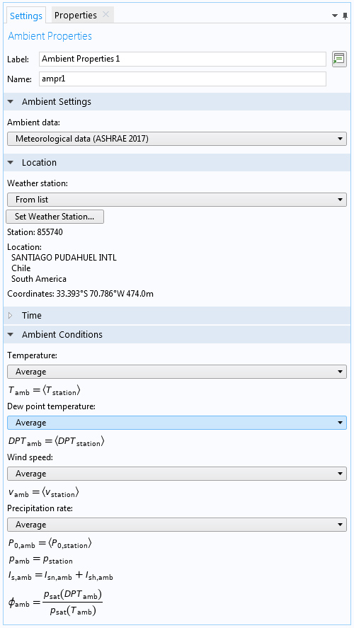
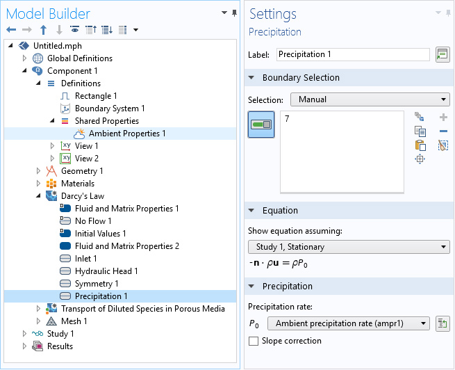
Ambient Properties
Ambient properties, such as temperature, relative humidity, absolute pressure, and wind velocity, can be defined from an Ambient Properties node under Definitions > Shared Properties. Along with the possibility of adding user-defined meteorological data, two meteorological datasets are available that contain ambient data from several weather stations in the world. These can be chosen to be computed from monthly- and hourly-averaged measurements from values provided in the ASHRAE 2013 and ASHRAE 2017 handbooks, which are collated from data measured by weather stations worldwide and provided by the American Society of Heating, Refrigerating, and Air-Conditioning Engineers (ASHRAE). When transient studies are performed, the climate data is automatically synchronized. Additionally, a new Precipitation boundary condition is added to the Darcy's Law interface, to account for the precipitation rate given by the Ambient Properties node.
New Reacting Flow in Porous Media Interface
With the new Reacting Flow in Porous Media, Transport of Diluted Species multiphysics interface, you can study the flow and chemical composition of a gas or liquid moving through the interstices of a porous medium. The multiphysics interface combines the Brinkman Equations and Transport of Diluted Species in Porous Media interfaces. The Reacting Flow, Diluted Species multiphysics coupling is added to couple fluid flow and mass transport. The chemical species are assumed to be solutes dissolved in a solvent of significantly higher concentration.
New Heat Transfer in Fractures Interface
With the new Heat Transfer in Fractures interface, you can study heat transfer in fractured porous media. With this interface, you do not need to represent the fracture thickness in the geometry. It provides a lumped model for cost-effective modeling and dedicated settings to define the fluid and the material properties. Additionally, the flow velocity in the fracture can be taken from the Fracture Flow interface.
New Adsorption Models
The Transport of Diluted Species in Porous Media and Transport of Diluted Species in Fractures interfaces include two new adsorption isotherms to predict the adsorption of dissolved species onto porous media. The Brunauer–Emmett–Teller (BET) and Toth isotherms are added to the existing Langmuir and Freundlich isotherms.
New Mass Inflow Boundary Conditions
The Inlet and Outlet boundary conditions in the Darcy's Law interface have been extended to include the possibility to specify the pressure and the mass flow in the Inlet node and the pressure in the Outlet node.
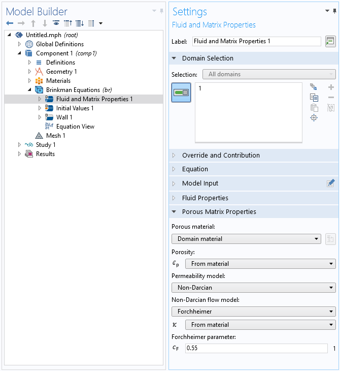
Non-Darcian Flow
Darcy's law and Brinkman's correction to Darcy's law only apply when the interstitial velocity in the pores is low enough that the creeping flow approximation holds. For higher interstitial velocities, an additional nonlinear correction can be added in the momentum equation. The Brinkman Equations, Free and Porous Media Flow, and Darcy's Law interfaces include non-Darcian settings for the permeability model. The available options are the Forchheimer and Ergun models for the Brinkman Equations, and Forchheimer, Ergun, Burke–Plummer, and Klinkenberg models for the Darcy's Law and Multiphase Flow in Porous Media interfaces.
New Tutorial Model
Version 5.5 brings a new tutorial model.
Frozen Inclusion
Application Library Title:
frozen_inclusion