Composite Materials Module Updates
For users of the Composite Materials Module, COMSOL Multiphysics® version 5.5 brings contact in layered shells, hyperelasticity, plasticity, piezoelectricity, activation, delamination, new failure criteria, and multiphysics couplings for layered shells in combination with fluid flow and acoustics. Learn more about all these Composite Materials Module updates in more detail below.
Piezoelectric Material in Layered Shell Interface
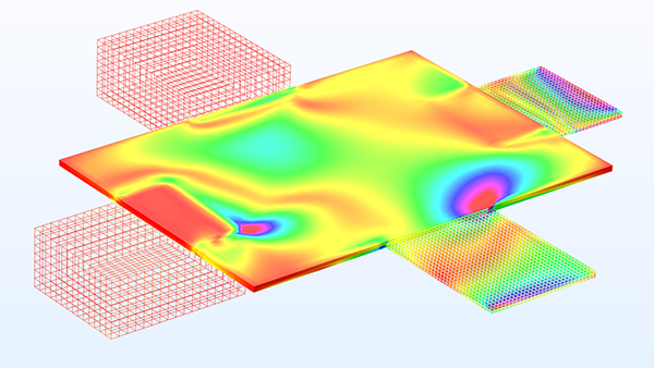
The addition of the piezoelectric material modeling capability to the Layered Shell interface makes it possible to model thin piezoelectric devices and sensors where a piezoelectric material is embedded in a composite laminate. A new multiphysics interface, Piezoelectricity, Layered Shell has been added for a convenient setup of models. It combines the two physics interfaces Layered Shell and Electric Currents in Layered Shells with a Layered Piezoelectric Effect multiphysics coupling. You can see this functionality in the new Piezoelectricity in a Layered Shell model. Note that to access this functionality, you need either the AC/DC Module or MEMS Module in addition to the Structural Mechanics Module and the Composite Materials Module.
Hyperelastic Material in the Layered Shell Interface
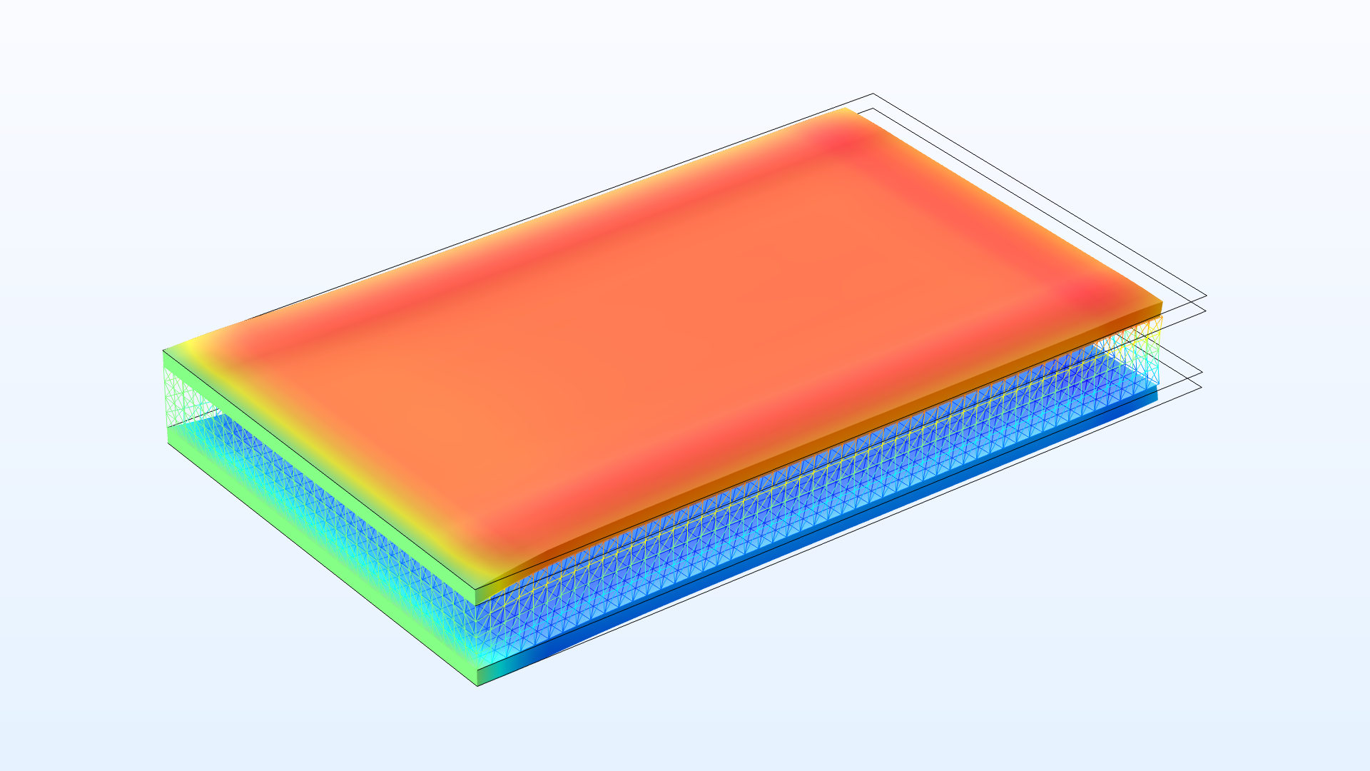
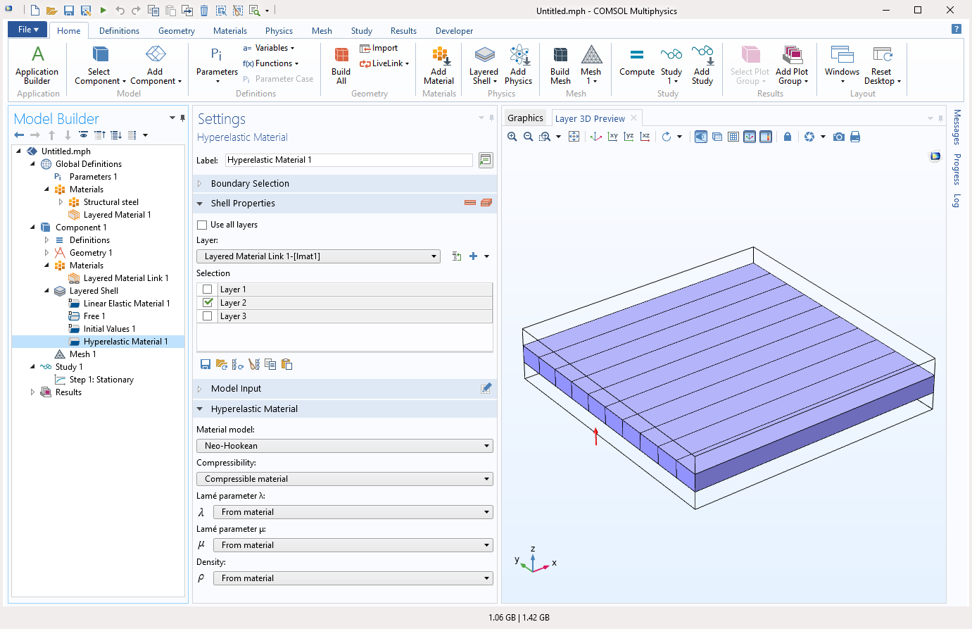
The addition of hyperelastic materials to the Layered Shell interface makes it possible to model large strains in composite shells where some of the layers are made up of rubber or other types of elastomers. Note that to access this functionality, you need the Nonlinear Structural Materials Module in addition to the Structural Mechanics Module and Composite Materials Module.
Plasticity in Layered Shells
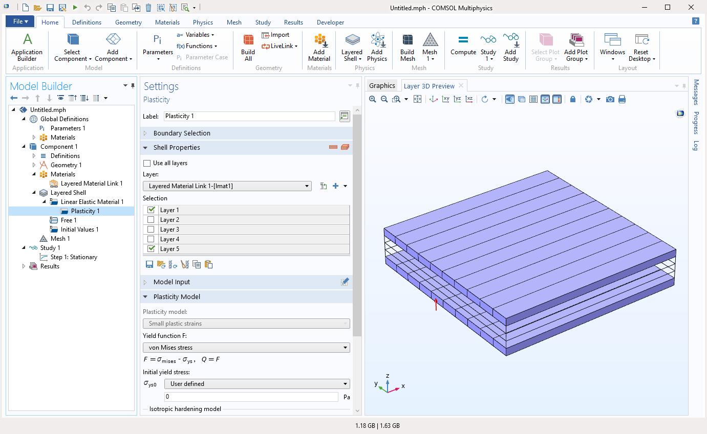
The addition of the Plasticity feature to the Linear Elastic Material node in the Layered Shell interface makes it possible to model plastic deformation in selected layers of a composite laminate, for example the outer metal layers in a sandwich structure. The plasticity models are the same as in the Solid Mechanics interface, with the exception that the plastic strains are assumed to be small. Note that to access this functionality, you need the Nonlinear Structural Materials Module in addition to the Structural Mechanics Module and Composite Materials Module.
Material Activation in Layered Shell Interface
The addition of the Activation feature to the Linear Elastic Material in the Layered Shell interface makes it possible to analyze the stress state in a composite laminate where certain layers are added or removed, which is useful when you want to model the addition of material during processes such as additive manufacturing.

Contact Modeling in the Layered Shell Interface
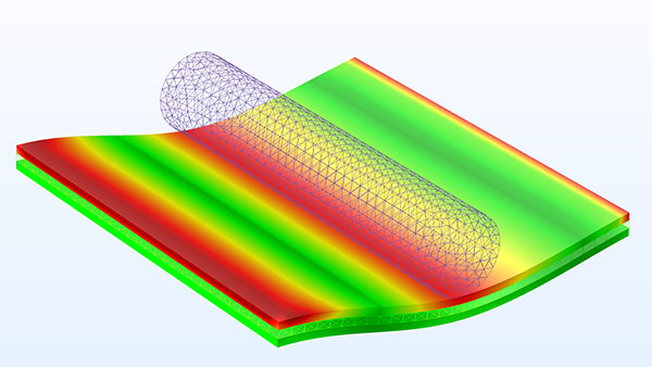
Contact modeling functionality has been added to the Layered Shell interface. You can analyze the contact between layered shell boundaries and boundaries modeled using other structural physics interfaces or even an arbitrary meshed surface having no physics interface attached. The contact is assumed to be frictionless.
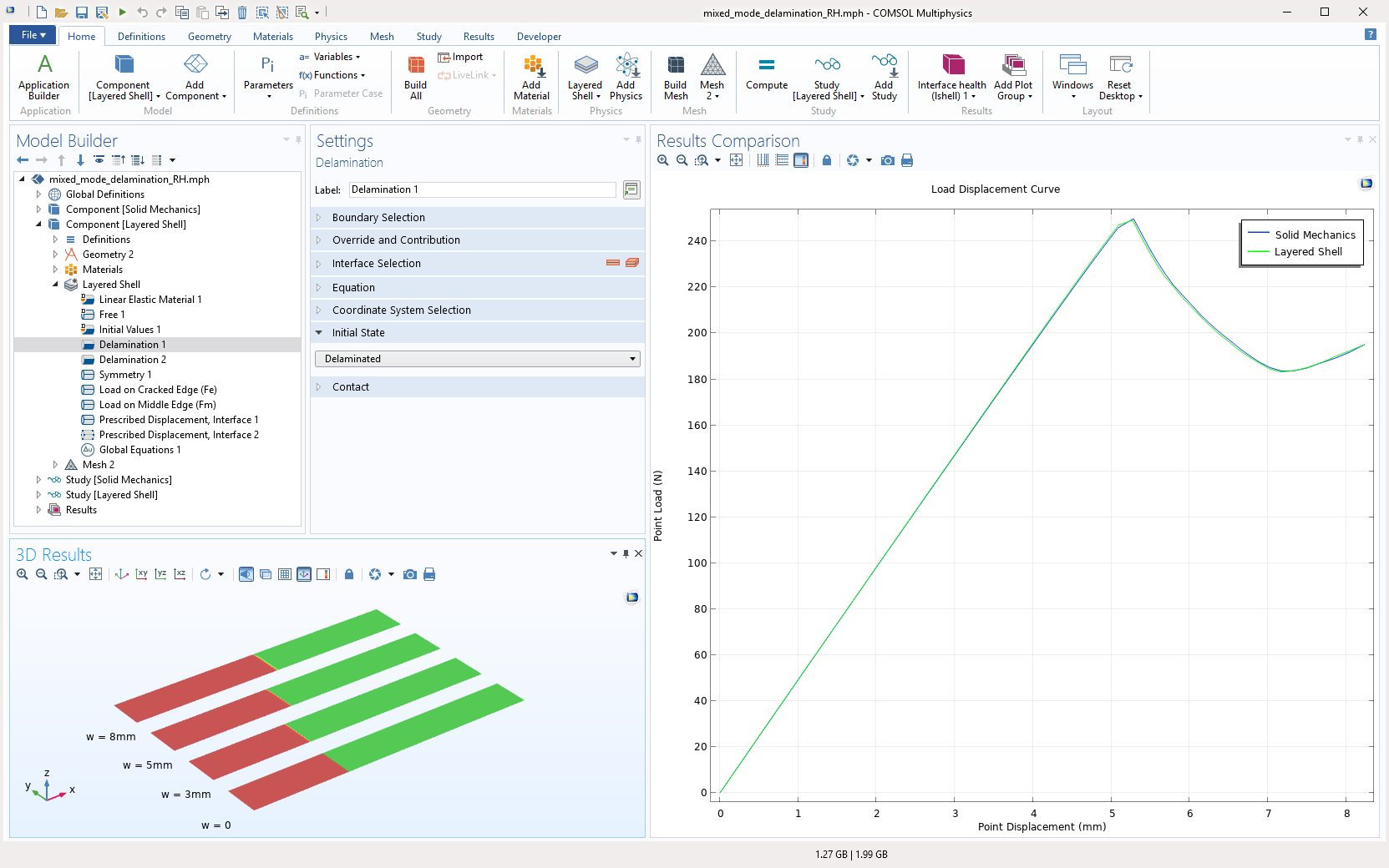
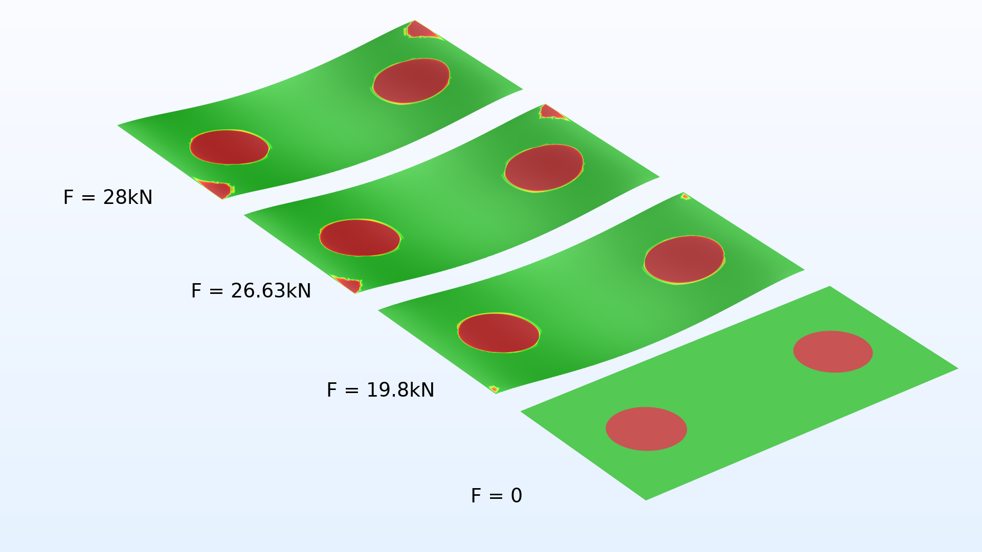
Delamination in the Layered Shell Interface
A common failure mode in layered composites is interfacial failure or delamination between the layers. You can now model progressive delamination using the new Delamination feature in the Layered Shell interface. There are several different displacement-based and energy-based cohesive zone models available for describing the damage together with different traction separation laws. When two layers are in a delaminated state, either initially or after applying a load, there will still be a contact condition to avoid penetration between the layers. This functionality is used in the Mixed-Mode Delamination of a Composite Laminate and Progressive Delamination in a Laminated Shell models.
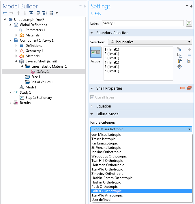
New Failure Criteria for Layered Shells
Using the Safety feature, you can assess the structural integrity using many different failure criteria. A set of new failure criteria have been added for fiber composites in the Layered Shell interface and in the Layered Linear Elastic Material node of the Shell interface. These new criteria are:
- Zinoviev
- Hashin–Rotem
- Hashin
- Puck
- LaRC03
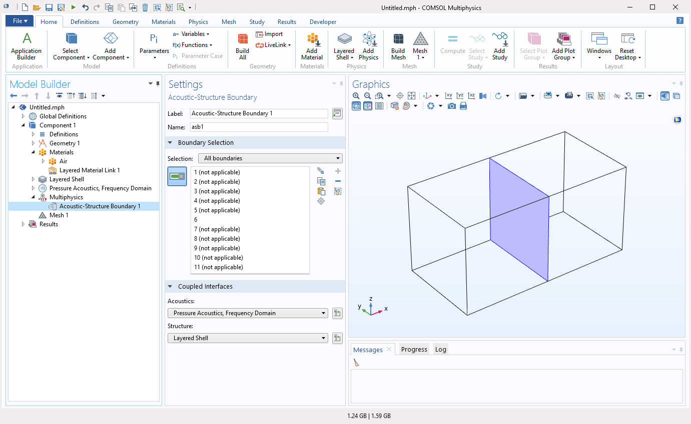
More Multiphysics Couplings for the Layered Shell Interface
More multiphysics couplings have been enabled for the Layered Shell interface to provide couplings with fluid flow and acoustics. You can now accurately model composite laminates interacting with fluid domains in different applications with the Fluid-Structure Interaction coupling. With the Acoustics Module, you can also model the Acoustics-Structure Boundary, Thermoviscous Acoustic-Structure Boundary, Aeroacoustics-Structure Boundary, and Porous-Structure Boundary multiphysics couplings.
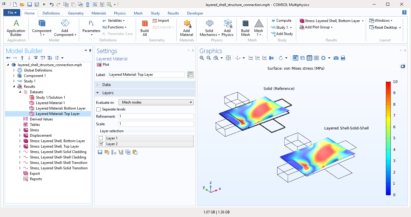
New Structural Couplings for the Layered Shell Interface
Composite laminates are often connected with solid or standard shell elements in different configurations to model real-world structures. Two new structural couplings have been added to the Layered Shell interface in order to provide different types of couplings to shell and solid elements: Layered Shell - Structure Cladding and Layered Shell - Structure Transition. This functionality is demonstrated in the Connecting Layered Shells with Solids and Shells model.

Layered Linear Elastic Material in the Shell and Membrane Interfaces
The Layered Linear Elastic Material functionality has improved integration with shells and membranes. This material model has been added to the Membrane interface where it can be used to model very thin laminates with low bending stiffness. Also, this material model can now be used in the Shell interface in 2D axisymmetry, whereas it was previously only available in 3D geometries.
In version 5.5, single-layer shells and membranes are accessible using the Structural Mechanics Module. With the Composite Materials Module, these analyses can be extended to multilayered shells and membranes, where each layer can be augmented to include thermal expansion or viscoelasticity. If you have the Nonlinear Structural Materials Module as well, plasticity and creep are also available.
Mixed Formulation in Layered Shells
Nearly incompressible materials can cause numerical problems if only displacements are used as degrees of freedom. To avoid such problems in a layered shell, pressure- and strain-based mixed formulations have been added to the Layered Shell interface.

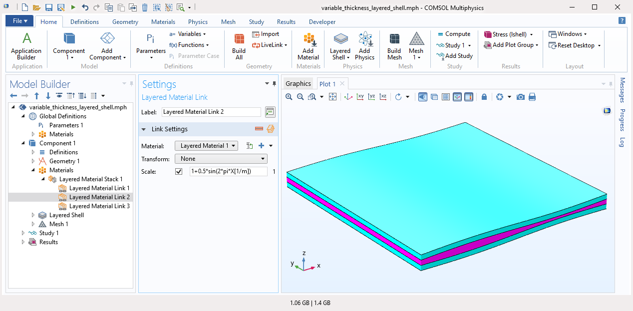
Variable Layer Thickness in Layered Shells
You can now model one or more layers of a composite laminate with a thickness that is a function of the coordinates. This new functionality is available through the new Scale setting in the Layered Material Link and Layered Material Stack nodes. Variable thickness layers are supported in the Layered Shell interface, as well as in the Layered Linear Elastic Material node in the Shell and Membrane interfaces.
Transform Option in Layered Materials
You can now perform various transformation operations while defining a laminate stacking sequence. This new functionality is available through the Transform setting in the Layered Material Link and Layered Material Stack nodes. The types of transforms are Symmetric, Antisymmetric, and Repeated. This makes it easier to model complex stacking sequences by defining only half of the stacking sequence for symmetric/antisymmetric laminates and a single unit in case of repeated laminates.
This functionality is used in the following models:
- composite_wheel_rim (new model)
- composite_cylinder_micromechanics_and_stress_analysis
- laminated_shell_material_characteristics

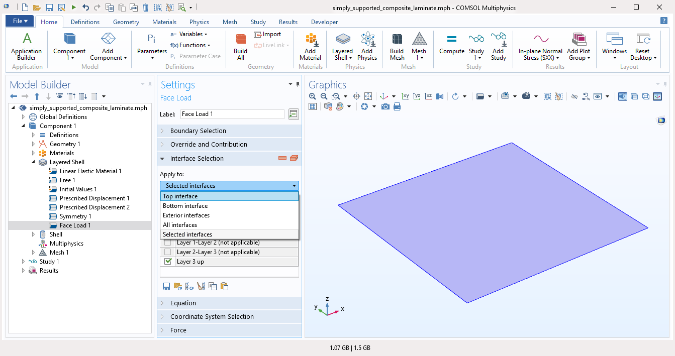
New Options for Interface Selection
In physics nodes that have the Interface Selection setting, there is now a direct way to select certain common interface locations: top, bottom, exterior, interior, or all. This makes the model setup more convenient and easier to understand. Some common applicable physics nodes in the Layered Shell interface are Face load, Delamination, and Thin Elastic Layer.
This feature is demonstrated in the following models:
- layered_shell_structured_connection (new model)
- mixed_mode_delamination (new model)
- simply_supported_composite_laminate
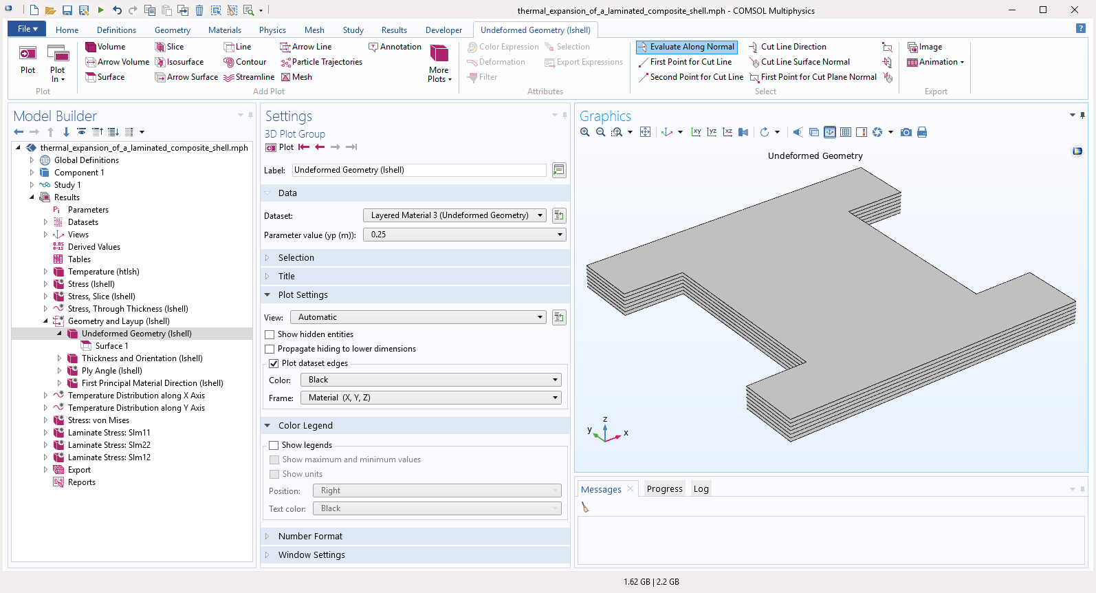
Visualization of 3D Solid Geometry
When modeling complex laminate structures, it is useful to visualize the corresponding 3D solid geometry, which is now shown automatically in a new default plot used in the Layered Shell interface. A gray surface plot is generated from the Layered Material (Undeformed Geometry) dataset.
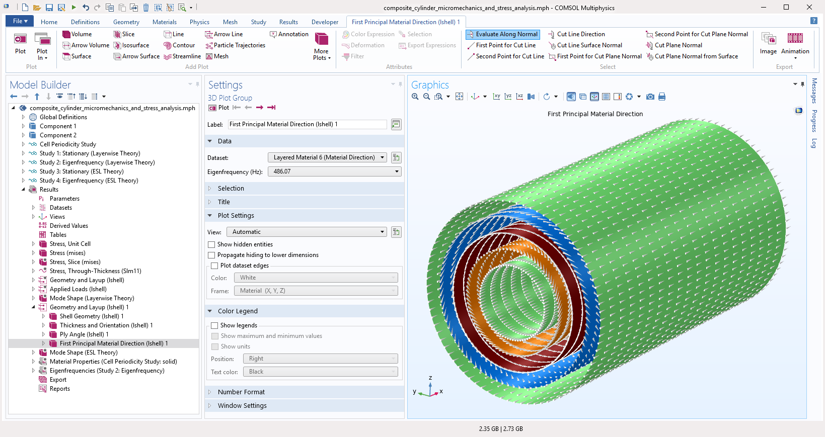
Visualization of Fiber Draping
When setting up a layered material model, the stacking sequence can be visualized using preview plots, created using an abstract geometry. However, there is often a need to visualize the fiber draping in the physical geometry. New in version 5.5, default plots are created to visualize the fiber direction in each ply in the physical geometry, applicable for models that use the Layered Shell or Shell interface.
Layered Material Dataset Enhancements
The Layered Material dataset, used to plot and evaluate the layered shell results, has new options for you to select layers or interfaces for evaluation. This makes postprocessing a composite laminate model easier, as only boundary selection was available previously. Also, there is a new through-thickness location option when evaluating in a Derived Values node. This functionality is demonstrated in the new Connecting Layered Shells with Solids and Shells model.
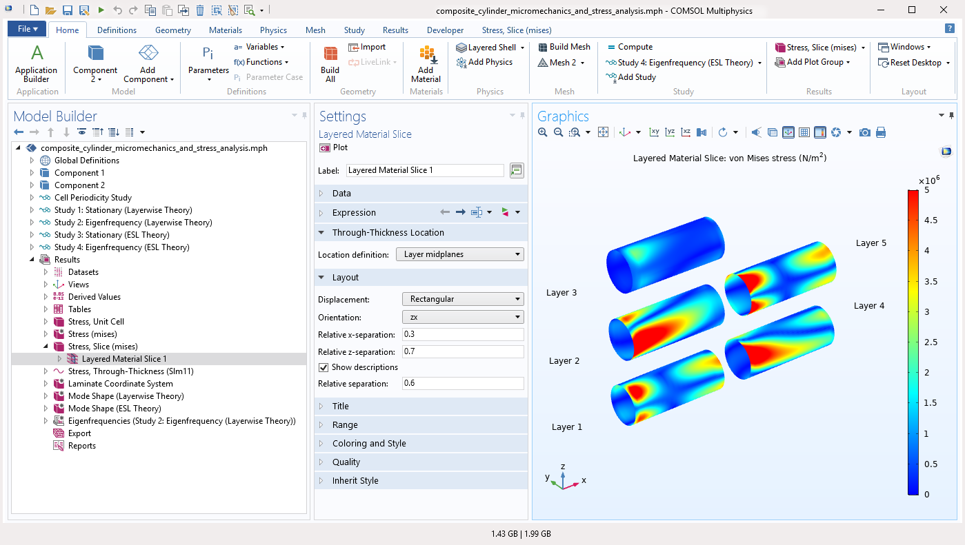
Layered Material Slice Plot Enhancements
The Layered Material Slice plot now has support for creating multiple slices automatically. Additionally, the following new functionality has been added in this release:
- Plotting on interfaces (previously only available on layers)
- Plotting on multiple layers using layer midplanes or similar options
- Defining a layout when using multiple slices
- Adding layer names to each slice
The Layered Material Slice plot is an important plot for composite laminates and the new functionality simplifies the steps required to plot results.
This functionality is demonstrated in the following models:
- Stress and Modal Analysis of a Composite Wheel Rim (new model)
- Mixed-Mode Delamination of a Composite Laminate (new model)
- Progressive Delamination in a Laminated Shell(new model)
- composite_cylinder_micromechanics_and_stress_analysis
- thermal_expansion_of_a_laminated_composite_shell
- wind_turbine_composite_blade
Through Thickness Plot Enhancements
For a composite laminate with a large number of layers, adding interface lines increases the clarity of a Through Thickness plot. In version 5.5, you can add these interface lines automatically. In addition to that, you can now plot the through thickness variation of a quantity that is defined only on a subset of the layers of a laminate.
This functionality is demonstrated in the following models:
- Stress and Modal Analysis of a Composite Wheel Rim (new model)
- forced_vibration_of_a_composite_laminate
- simply_supported_composite_laminate
- wind_turbine_composite_blade
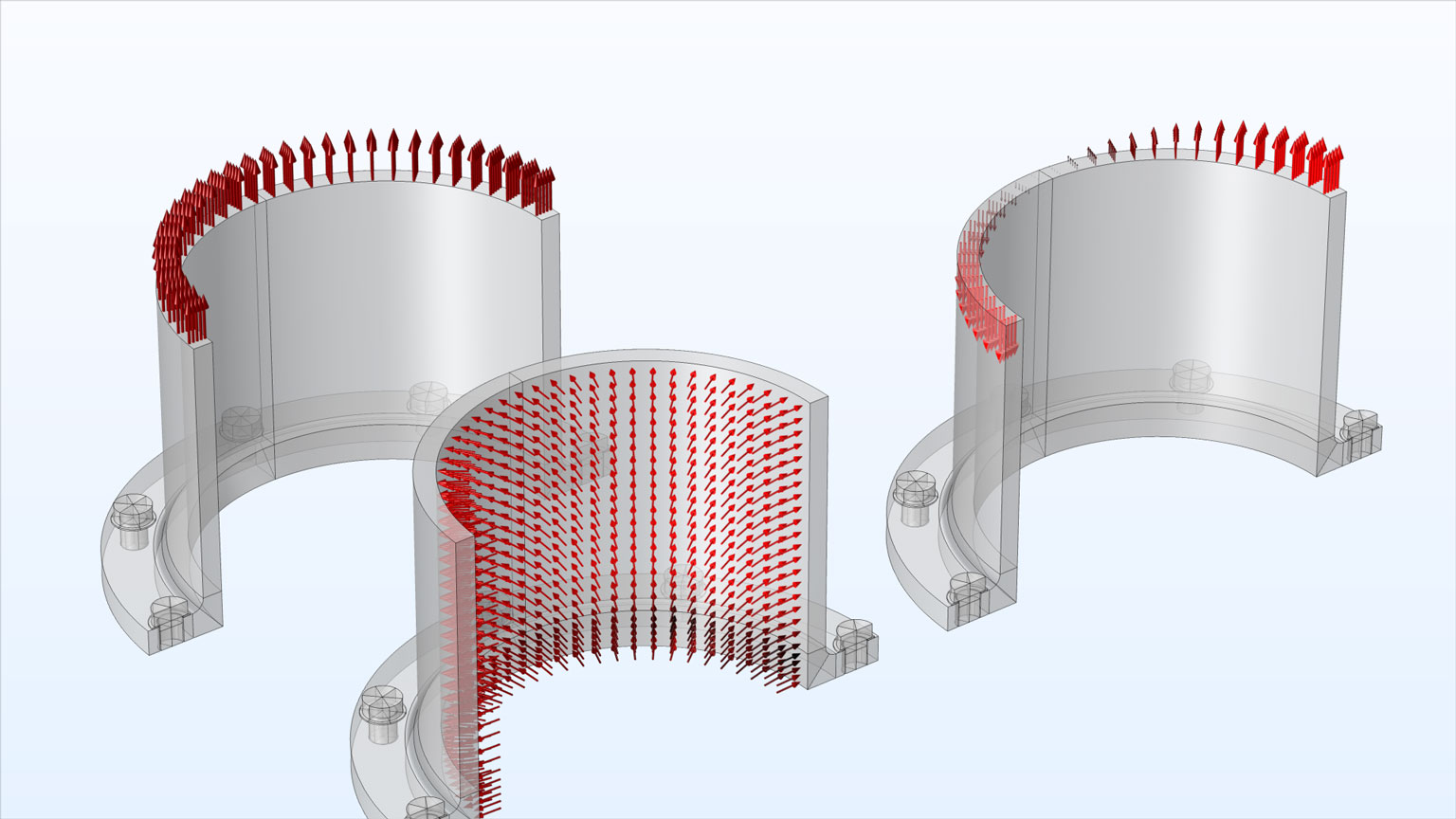
Visualization of Loads
Applied mechanical loads are now available as default plots in all structural mechanics physics interfaces. The loads plots are solution dependent, so both arrow directions and colors are updated when a dataset is updated with a new solution. Even abstract loads, such as forces and moments applied to rigid connectors and rigid domains, are plotted at their true point of application. A new arrow type, used for plotting applied moments, has been introduced for this functionality. More than 100 models are updated with this new functionality.
New Tutorial Models and Applications
Version 5.5 brings several new tutorial models and applications.
Progressive Delamination in a Laminated Shell
Application Library Title:
progressive_delamination_in_a_laminated_shell
Mixed-Mode Delamination of a Composite Laminate

Application Library Title:
mixed_mode_delamination
Stress and Modal Analysis of a Composite Wheel Rim
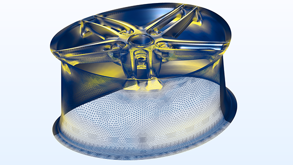
Application Library Title:
composite_wheel_rim
Piezoelectricity in a Layered Shell
Application Library Title:
piezoelectric_layered
Connecting Layered Shells with Solids and Shells
Application Library Title:
layered_shell_structure_connection