Pipe Flow Module Updates
For users of the Pipe Flow Module, COMSOL Multiphysics® version 5.5 brings a new physics interface to perform stress analysis in pipe systems, a new multiphysics coupling to couple pressure acoustics to pipe acoustics, and an automatic search for T- and Y-junctions in a pipe system. Read more about these features below.
Mechanical Analysis of Pipes
The new Pipe Mechanics interface provides functionality for performing stress analysis of pipe systems. In addition to external mechanical loads, you can account for internal pressure, axial drag forces, and temperature gradients through the pipe wall. The fluid loads can be taken directly from the Pipe Flow interface, and the temperatures can be taken from the Heat Transfer in Pipes interface. You can see this new interface in the Coupled Analysis of Flow and Stress in a Pipe model.
Acoustic-Pipe Acoustic Connection Multiphysics Coupling
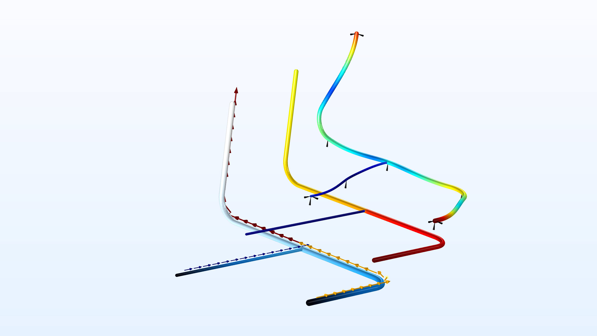
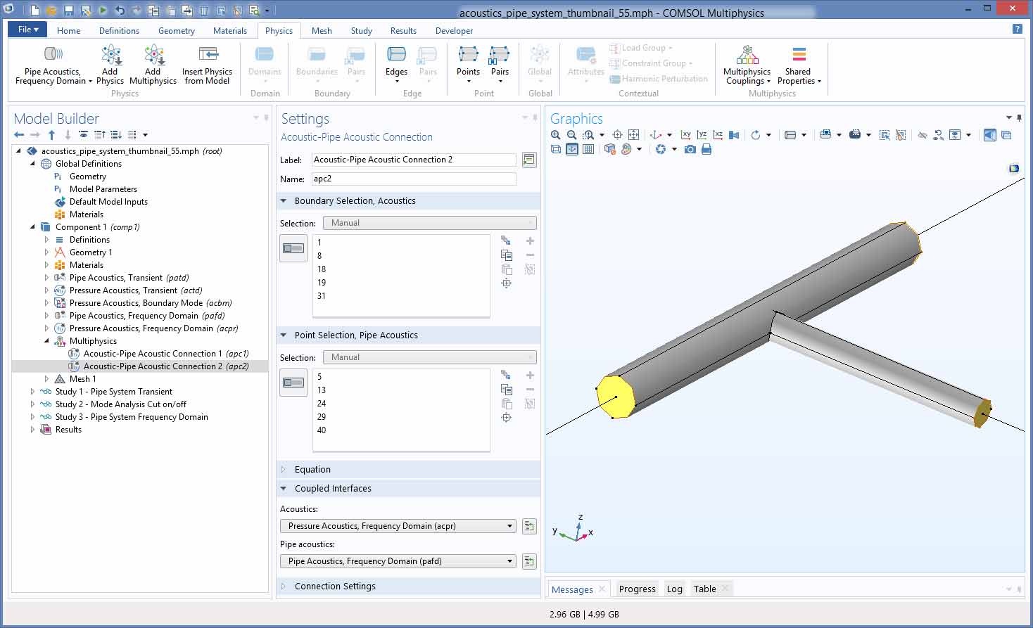
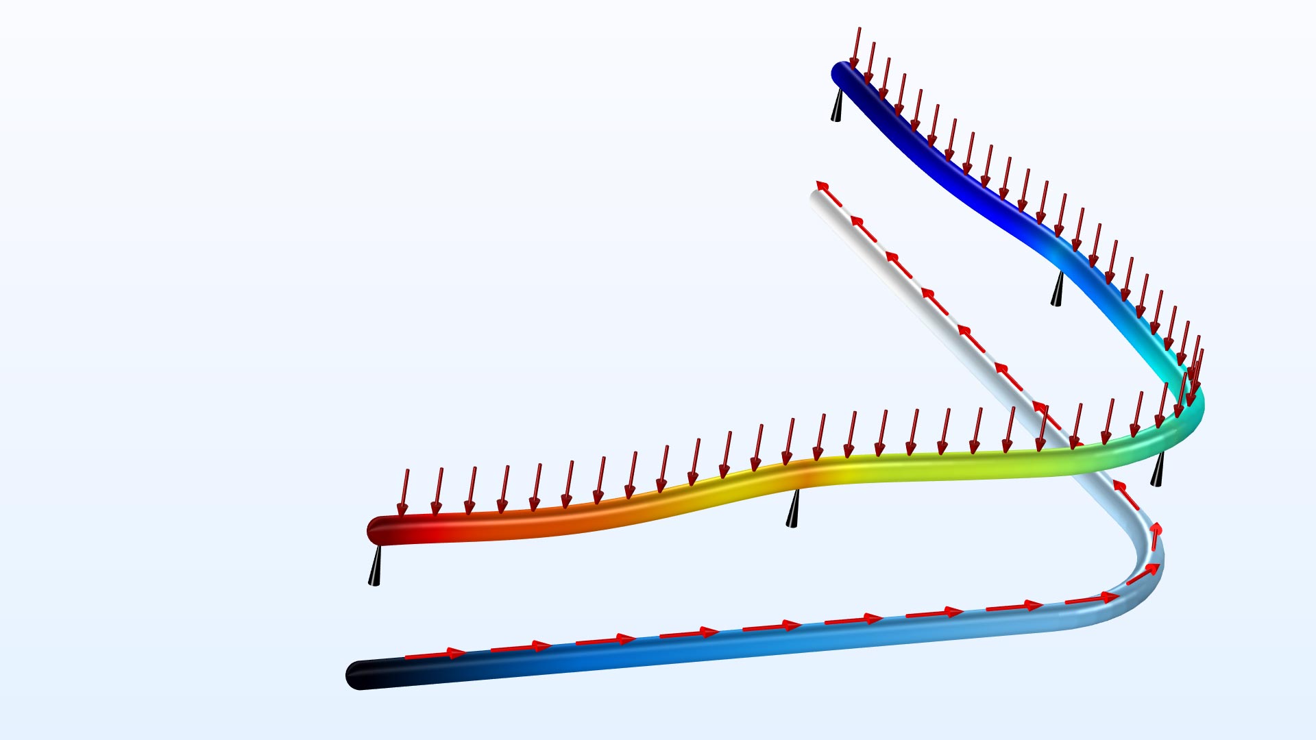
With the new Acoustic-Pipe Acoustic Connection multiphysics coupling, you can couple the pressure acoustics interfaces to the pipe acoustics interfaces in both frequency and time domain simulations. The coupling is defined between a point in the pipe interface and a boundary in the pressure acoustics interface. You can see this functionality used in the Probe Tube Microphone and Acoustics of a Pipe System with 3D Bend and Junction models.
Automatic Selection of T-Junctions and Y-Junctions
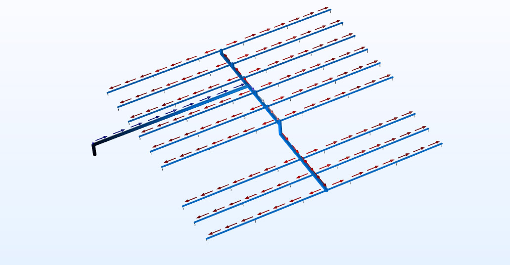
The software can now automatically add T- and Y-junctions in your pipe system to the selection, based on the angles between the branches in a junction. This significantly simplifies the modeling of large pipe networks, as you do not need to select the points manually. The default is still a manual selection, but you can uncheck a new Manual control of selections box, and the software will add the appropriate points to the selection. You can also check the Enable physics symbols box in the Pipe Flow interface node to view the symbols in the Graphics window.

New Tutorial Models
Version 5.5 brings three new tutorial models.
Coupled Analysis of Flow and Stress in a Pipe
Application Library Title:
pipe_flow_stress
Acoustics of a Pipe System with 3D Bend and Junction
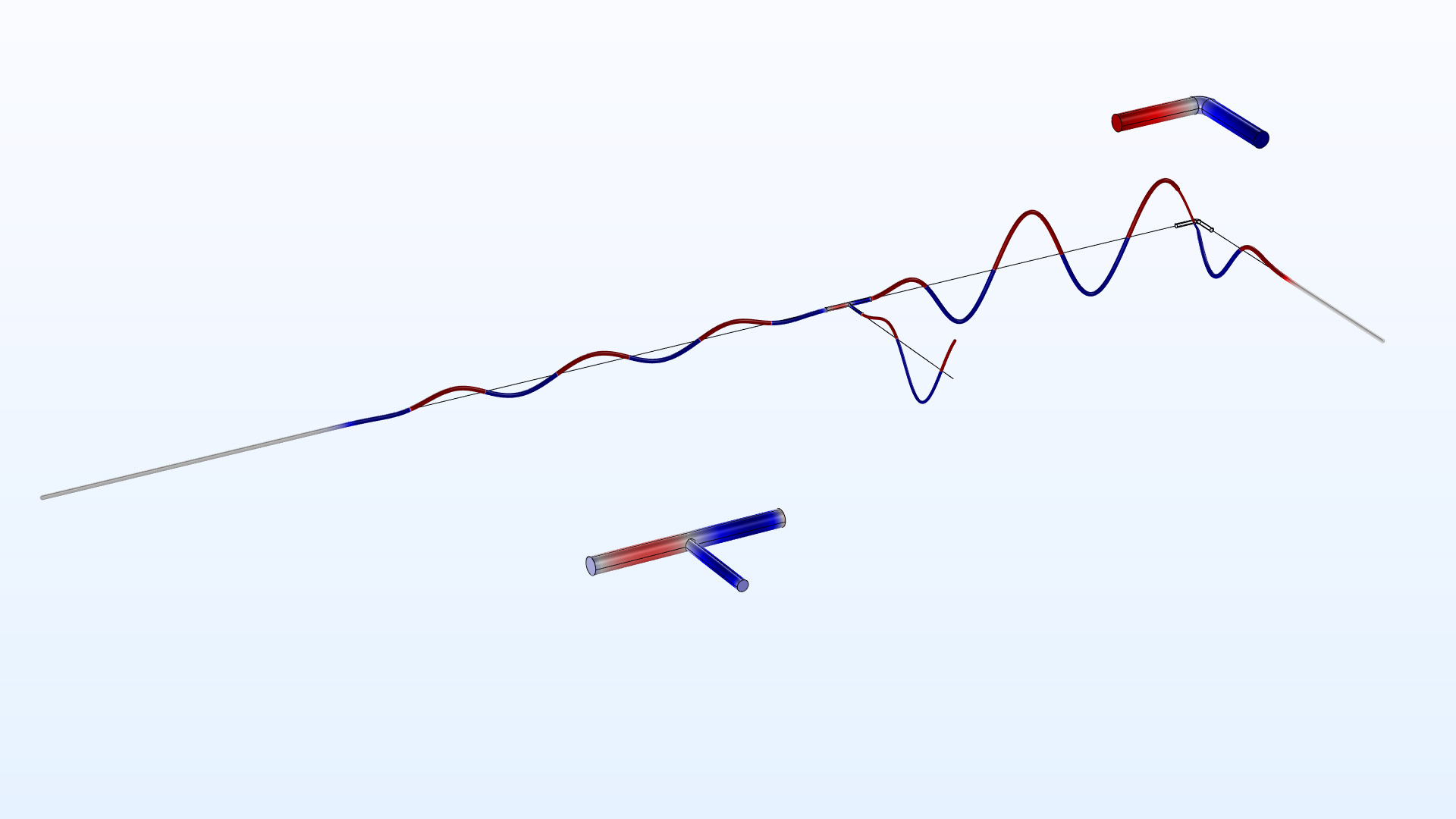
Application Library Title:
acoustics_pipe_system
Probe Tube Microphone
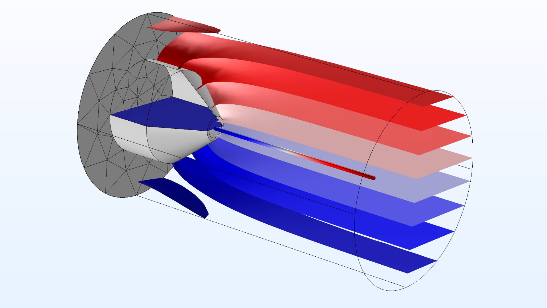
Application Library Title:
probe_tube_microphone