Structural Mechanics Module Updates
For users of the Structural Mechanics Module, COMSOL Multiphysics® version 5.5 brings contact modeling to shells and membranes, plasticity, creep, viscoplasticity and viscoelasticity availability for shells, and a physics interface for the mechanical analysis of pipes. Browse these structural mechanics features and more below.
Contact Modeling Extensions
The contact modeling functionality has been extended to more physics interfaces, now available in: Solid Mechanics, Multibody Dynamics, Shell (new), Layered Shell (new), and Membrane (new). Additionally, you can analyze contact between boundaries modeled with any two of these interfaces. Similarly, contact can be modeled between a boundary on which any of these interfaces is active, and an arbitrary meshed part, even if the latter does not have physics assigned to it.
You can see this new functionality in the following models:
- block_on_arch (new model)
- instability_two_contacting_arches (new model)
- contacting_rings
- snap_hook
- snap_hook_penalty
- transient_rolling_contact
- hyperelastic_seal

Plasticity, Creep, Viscoplasticity, and Viscoelasticity Extensions
The Plasticity, Creep, Viscoplasticity, and Viscoelasticity features, intended for modeling inelastic deformations in metals and alloys, are now available in the Shell interface. This is important for reducing computational time when modeling thin-walled structures. You can control the balance between accuracy and computation time by selecting the number of integration points in the through-thickness direction. You can see this new feature in the Twisting and Bending of a Metal Frame and Pressurized Orthotropic Container - Shell Version models.

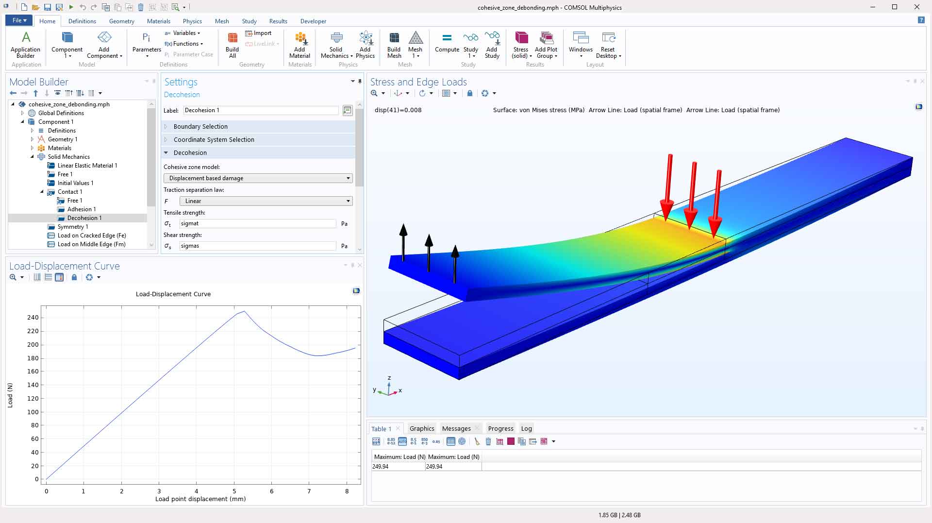
Decohesion Enhancements
There are now two fundamental families of decohesion models: Displacement based damage and the new Energy based damage. Additionally, you can set up models with a new traction separation law, Exponential separation. Decohesion models are inherently unstable, due to the loss of material stiffness, and to improve the numerical behavior, you can include a Delayed damage regularization method.
Multiphysics Interface for FSI with Heat Transfer
In some fluid-structure interaction (FSI) problems, heat transfer between the fluid and the solid is important. Usually, this is also accompanied by thermally induced deformations or stresses in the solid. A new multiphysics interface, Fluid-Solid Interaction, Conjugate Heat Transfer has been added to make it convenient to set up models combining these effects. It combines the three physics interfaces Heat Transfer in Solids and Fluids, Solid Mechanics, and Laminar Flow together with a moving mesh and appropriate multiphysics couplings. As with all other FSI interfaces, the flow can easily be changed from laminar to be turbulent. You can see this new feature in the Bimetallic Strip in Airflow model.

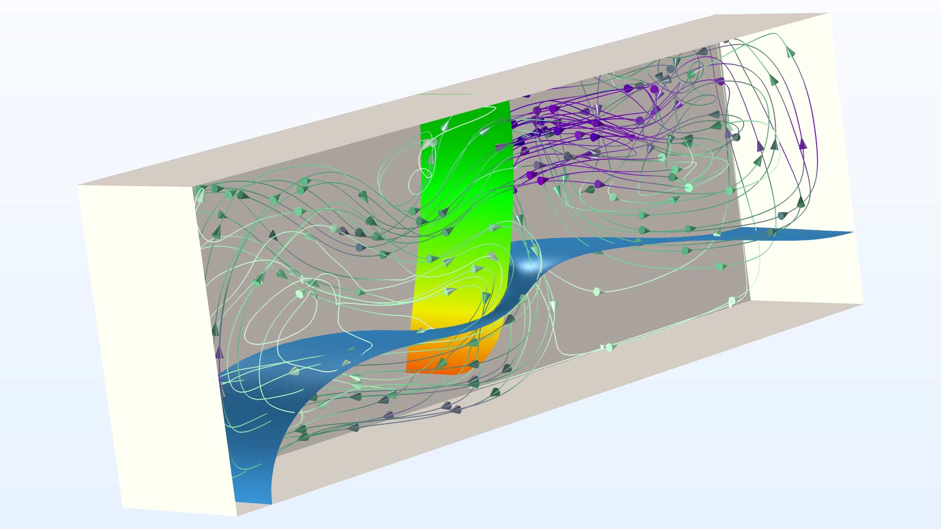
Fluid-Structure Interaction for Two-Phase Flows
The suite of multiphysics interfaces for fluid-structure interaction has two new entries for two-phase flows: Fluid-Solid Interaction, Two-Phase Flow, Phase Field and Fluid-Solid Interaction, Two-Phase Flow, Phase Field, Fixed Geometry_. When you select the Fluid-Solid Interaction, Two-Phase Flow, Phase Field option from the Model Wizard, the Laminar Flow, Solid Mechanics, and Phase Field interfaces are added, along with the Fluid-Structure Interaction and Two-Phase Flow multiphysics couplings and a Deforming Domain feature. The fixed geometry option includes the same, minus the Deforming Domain feature. You can see this new functionality in the Two-Phase Flow with Fluid-Structure Interaction model.
Mechanical Analysis of Pipes
The new Pipe Mechanics interface provides functionality for performing stress analysis of pipe systems. In addition to external mechanical loads, you can account for internal pressure, axial drag forces, and temperature gradients through the pipe wall. The fluid loads can be taken directly from the Pipe Flow interface, and the temperatures can be taken from the Heat Transfer in Pipes interface. You can see this new interface in the Coupled Analysis of Flow and Stress in a Pipe model.
Solid Mechanics on Rotating Domains
When modeling multiphysics problems in systems where there is a mixture of rotating and stationary domains, you can use the Solid Mechanics interface in a corotating configuration, such that only the deformations relative to the rotation are modeled. This is far more efficient than solving for the total displacements that include large global rotations. In many cases, it is even possible to use a linear formulation for the mechanical problem. To this end, the Rotating Frame feature provides a superposition of the rigid body rotation, and the relative displacements, for controlling the spatial frame on which the other physics interfaces are operating.

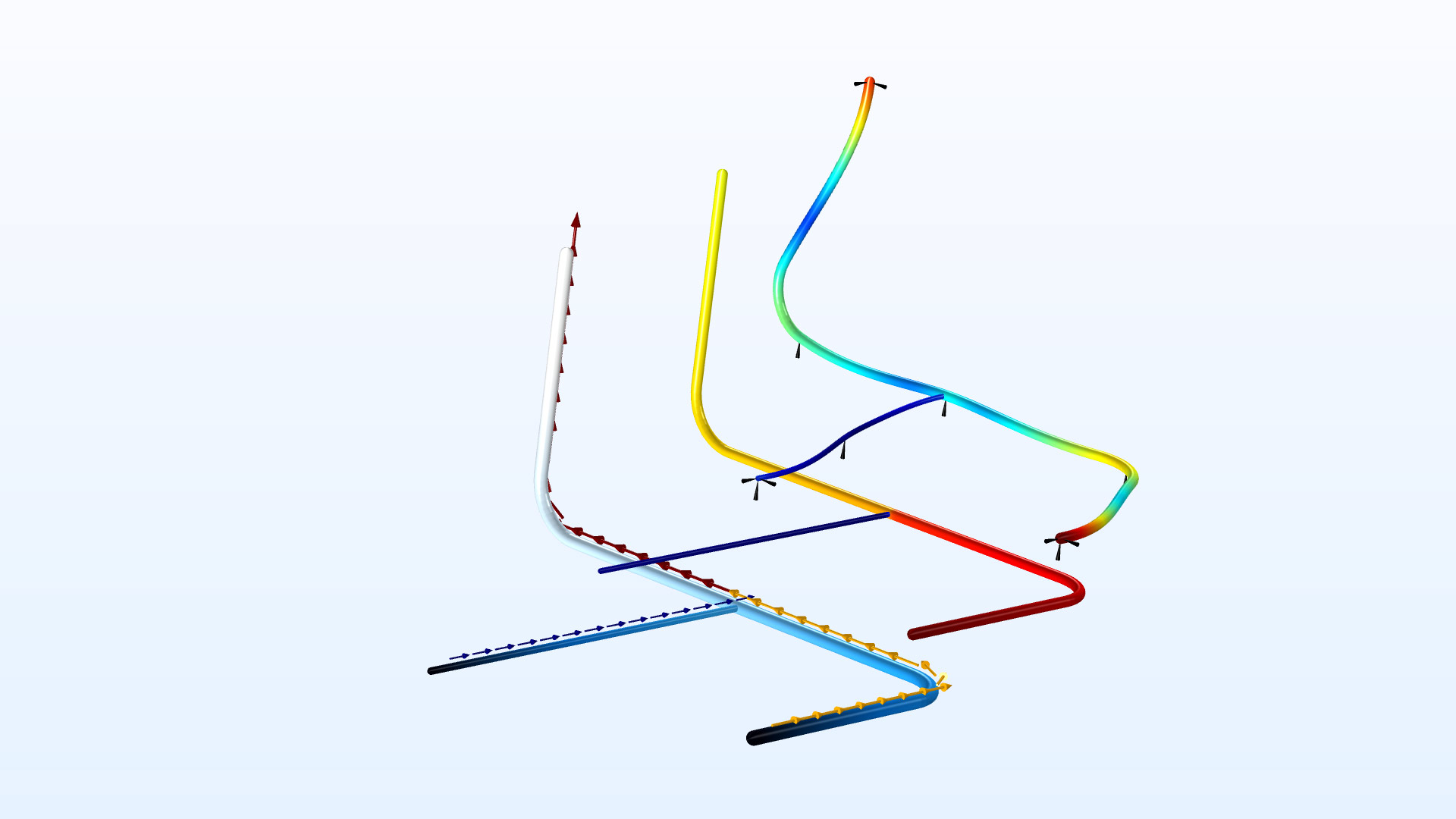
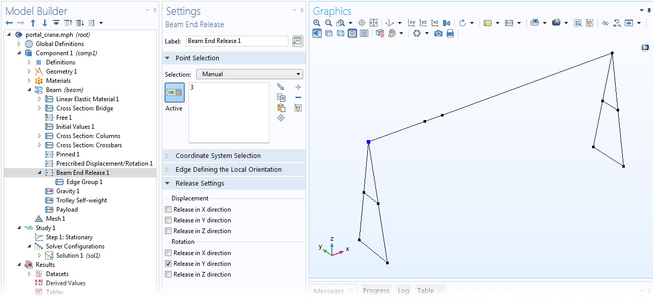
Nonrigid Joints Between Beams
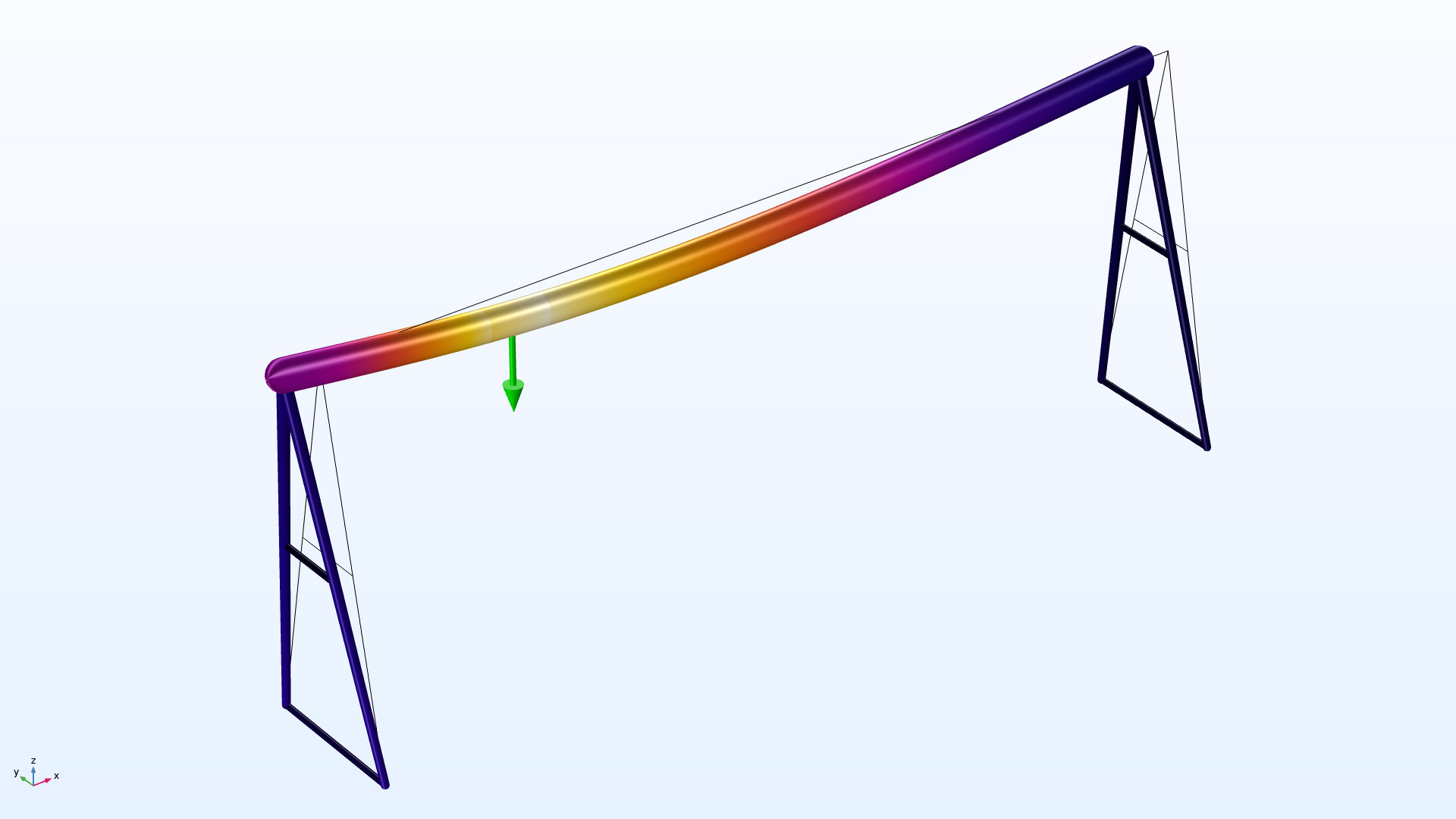
In the Beam interface, you can specify that two (or more) edges that meet at a point have disconnected degrees of freedom. Using the new Beam End Release feature, you select the point where there is a discontinuity and in what direction (displacement and/or rotation) to release the beam end. This can be used for modeling internal hinges or other mechanisms in a frame, as demonstrated in the new Stress Analysis of a Portal Crane model.
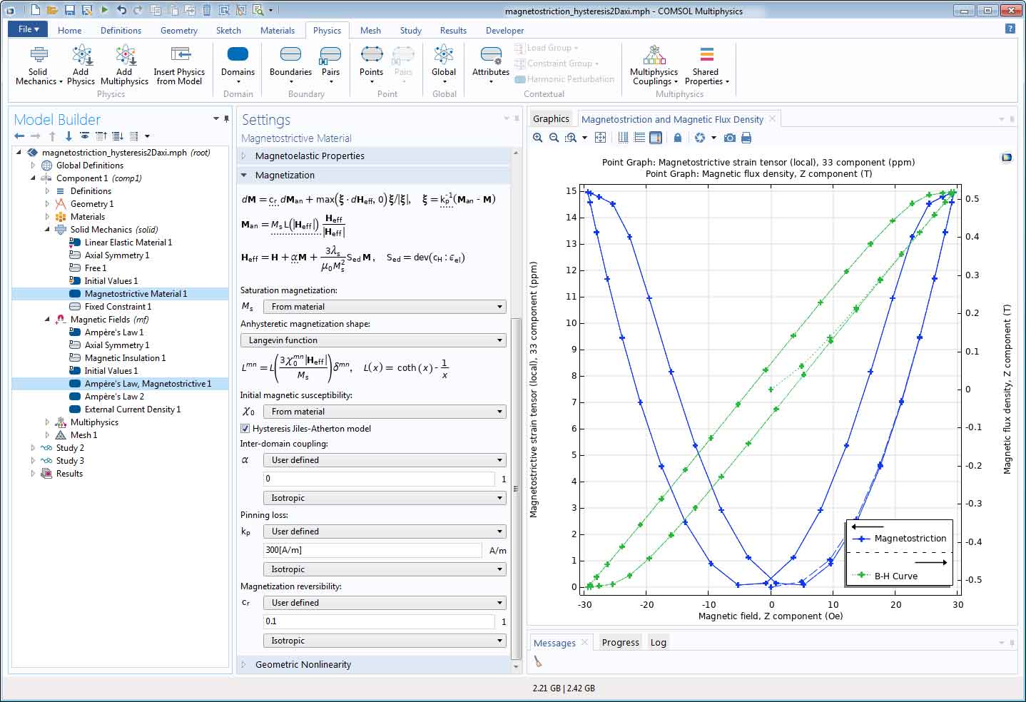
Magnetostrictive Material with Hysteresis
The nonlinear Magnetostrictive Material has been extended to include the Jiles–Atherton model of magnetic hysteresis. The model is suitable for investigating the hysteretic loss effects in applications such as power transformers and rotating electric machines. The model parameters are related to microscopic physical effects in magnetic materials and they can also be estimated based on experimental data.
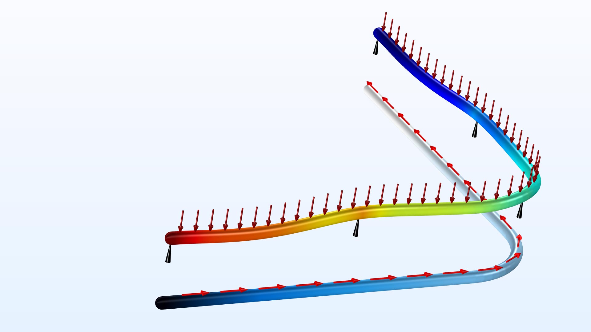
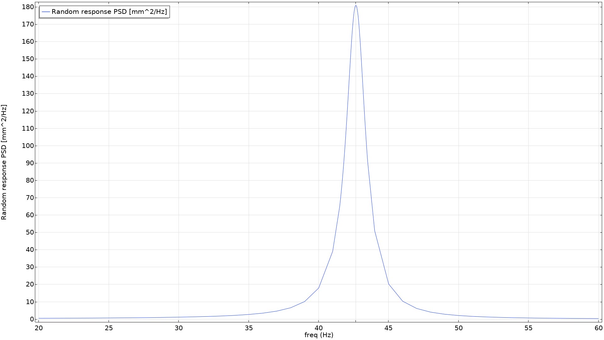
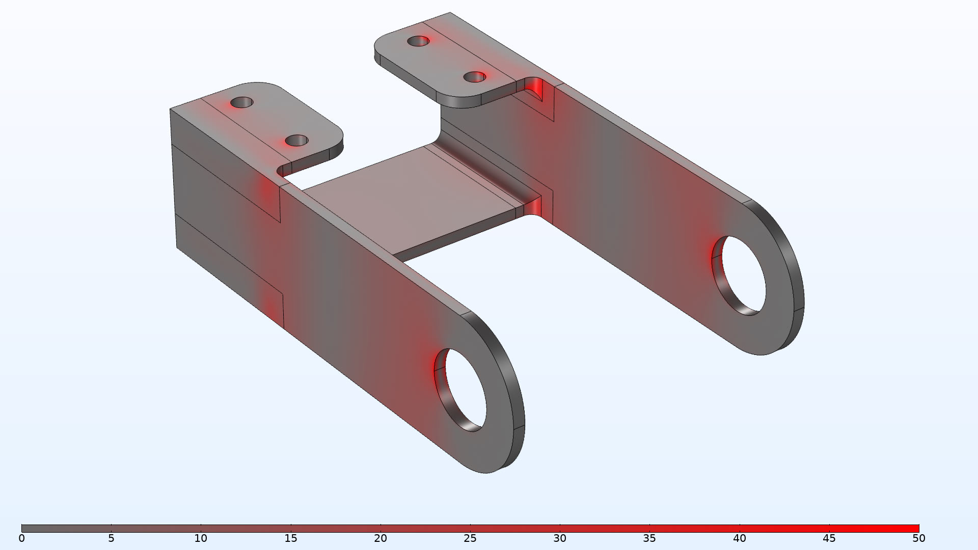
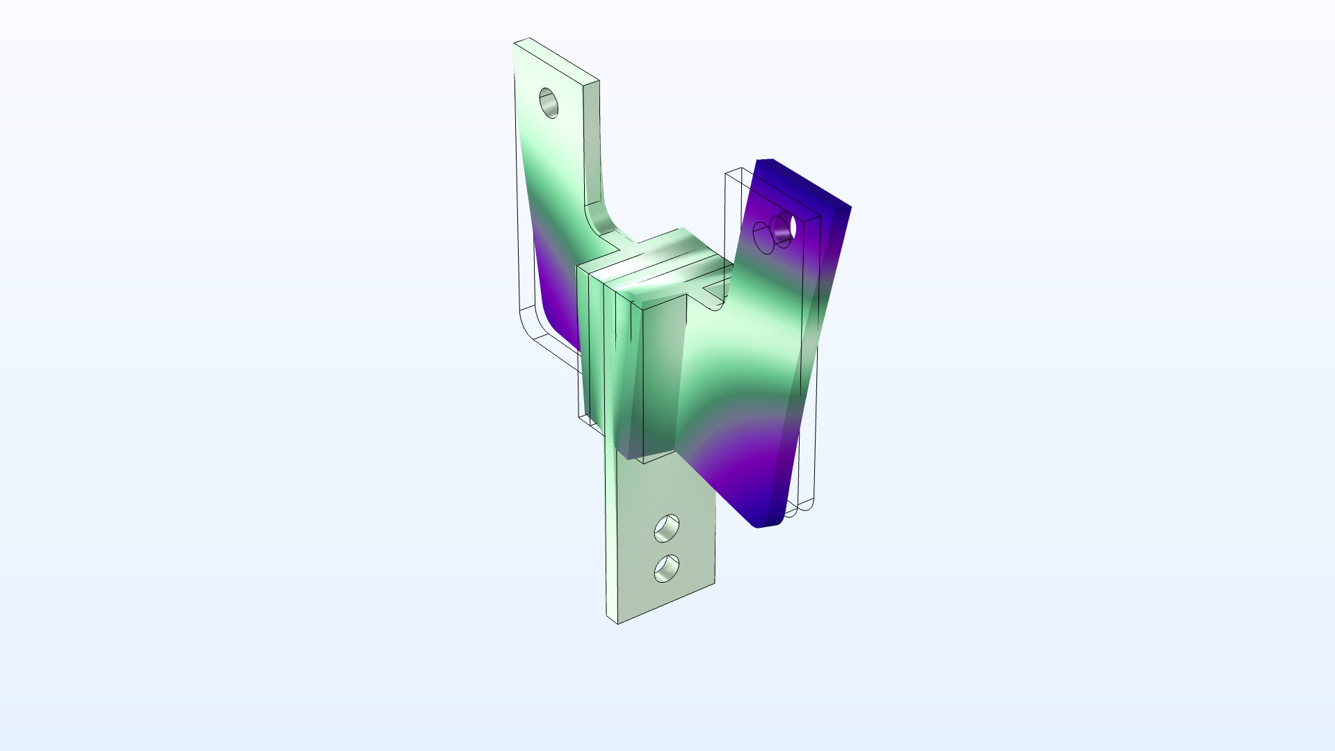
Random Vibration Analysis
When loads are random in nature, such as turbulent wind gusts or road-induced vibrations on a vehicle, it is not possible to describe them in a deterministic way. Using the new functionality for random response analysis, you can study the response to loads that are represented by their power spectral density (PSD). The loads can be fully correlated, uncorrelated, or have a specific user-defined cross-correlation. Examples of computed results include PSDs of displacements or stresses, as well as the root mean square (RMS) value or higher moments of the spectral distributions.
This new functionality is demonstrated in the following models:
- Random Response Analysis of a Deep Beam (new model)
- Bracket — Random Vibration Analysis (new model)
Visualization of Loads
Applied mechanical loads are now available as default plots in all structural mechanics physics interfaces. The loads plots are solution dependent, so both arrow directions and colors are updated when a dataset is updated with a new solution. Even abstract loads, such as forces and moments applied to rigid connectors and rigid domains are plotted at their true point of application. A new arrow type, used for plotting applied moments, has been introduced for this functionality. More than 100 models are updated with this new functionality.

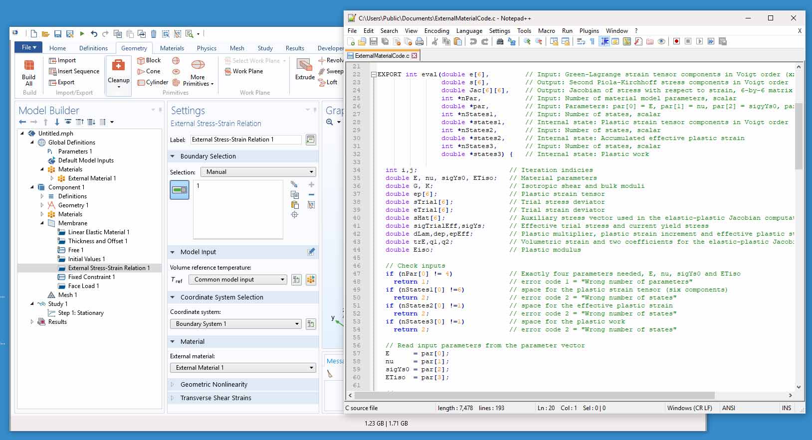
User-Defined Material for Membranes
The External Stress-Strain Relation material model has been added to the Membrane interface. With this material model, you can add your own material models, coded in C or other programming languages.
Point Selections in Rigid Connector for Shell
You can now select points and edges for the selection in a Rigid Connector feature in the Shell interface. With this, you can add a rigid connector that is only connected to a set of points, by adding it at the point level. This makes it easier to create simplified bolted or riveted connections, for example.
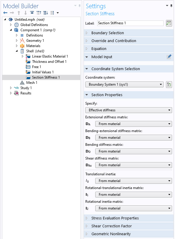
Direct Stiffness Input for Shells and Plates
In the Shell and Plate interfaces, it is now possible to describe the elastic stiffness of a cross section in terms of membrane and bending stiffness, rather than by material data and thickness. This new Section Stiffness material model facilitates the modeling of homogenized complex structures, such as corrugated sheets. As an alternative, you can provide the input on a flexibility form.
In a general case, it is difficult to compute stresses directly in homogenized materials, since the local details are removed. This type of material model is thus most useful when only the stiffness is important. However, you do have the option of entering expressions for how to compute stresses from section forces for cases when such an operation is well defined.
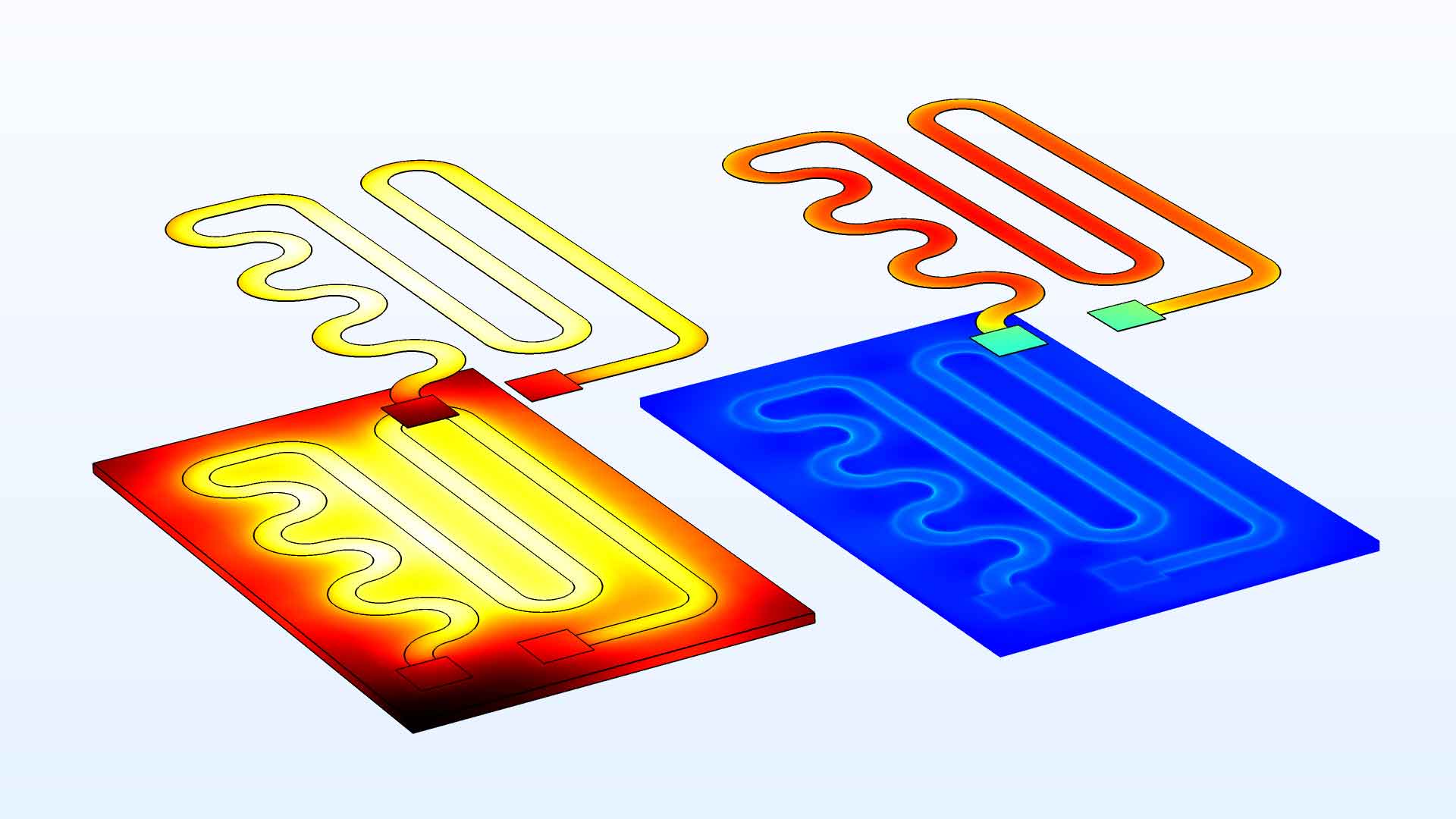
Multiphysics Coupling for Heat Transfer in Thin Structures
Effects of thermal expansion can be important in solids as well as thin structures like shells and membranes. Multiphysics couplings have been added so that temperatures computed in a heat transfer analysis of a thin structure can be automatically transferred to corresponding structural mechanics interfaces.
To this end, three new multiphysics interfaces have been added:
- Thermal Stress, Shell, combining the Heat Transfer in Shells and Shell interfaces
- Thermal Stress, Layered Shell, combining the Heat Transfer in Shells and Layered Shell interfaces
- Thermal Stress, Membrane, combining the Heat Transfer in Shells and Membrane interfaces
You can also connect to the structural mechanics interfaces from the Thin Layer feature within the Heat Transfer in Solids interface.
View this functionality in the updated Heating Circuit model.
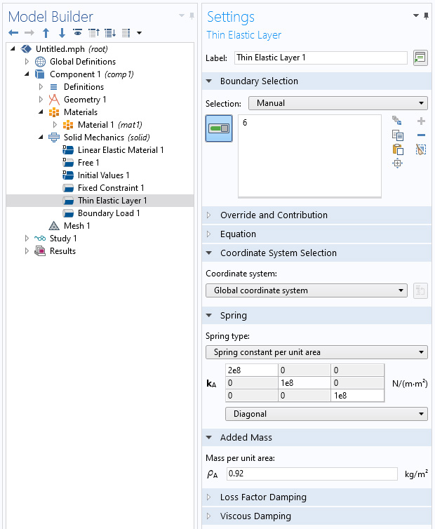
Thin Elastic Layers with Mass
The Thin Elastic Layer feature, intended for abstract modeling of layers that are thin compared to the rest of the geometry, has been augmented by a possibility to add a mass distribution. This can be important for high-fidelity structural dynamics simulations.
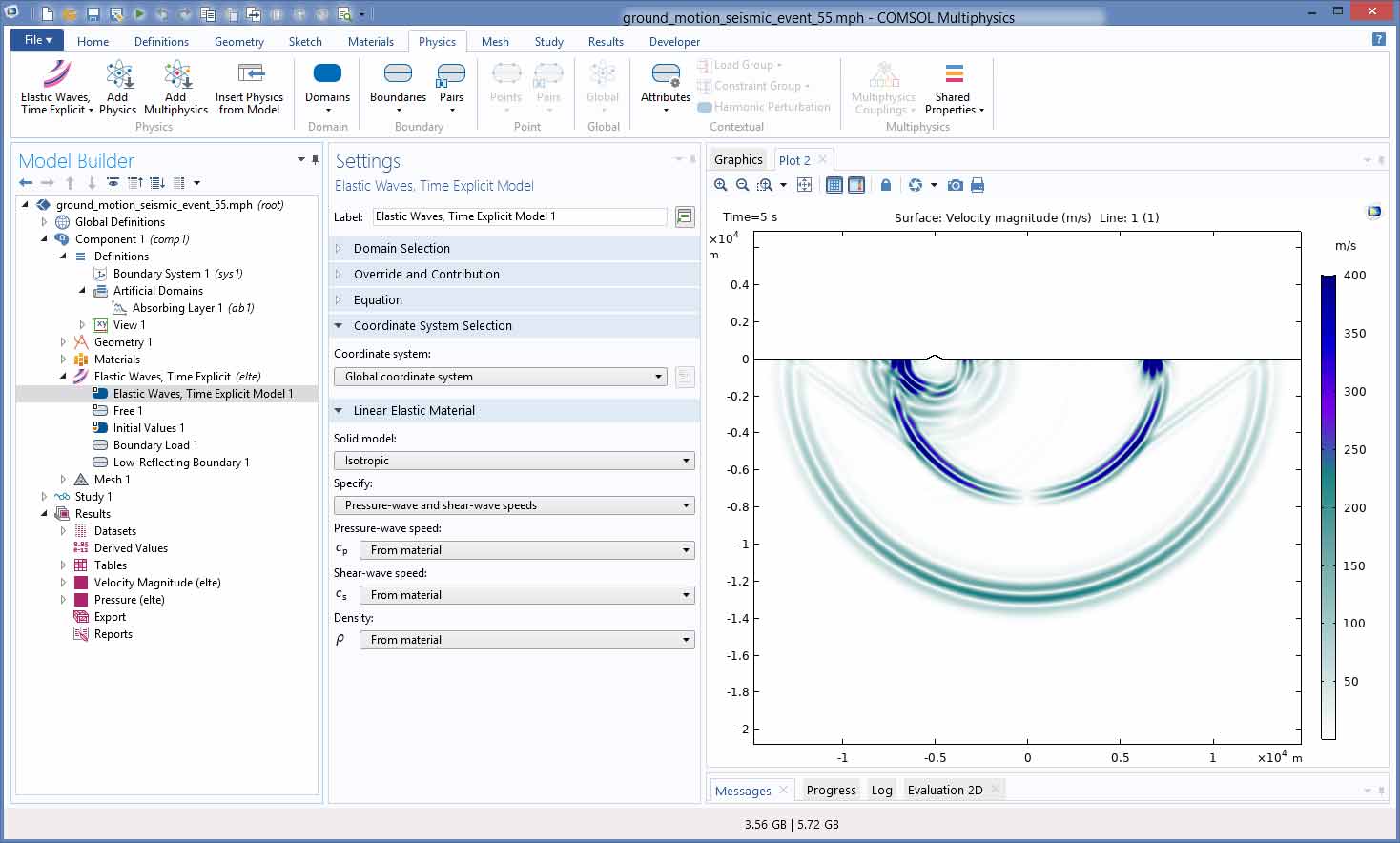
New Elastic Waves, Time Explicit Physics Interface
The new Elastic Waves, Time Explicit physics interface is based on the discontinuous Galerkin time explicit method and enables efficient multicore computations of elastic wave propagation in solids. Features are included to provide realistic material data including anisotropy and damping. The interface is suited for modeling ultrasound propagation in solids, such as with transducers and sensors, and for nondestructive testing (NDT) applications, and is applicable to any acoustically large system that involves transient propagation over many wavelengths, which includes seismic wave propagation in soil and rock.
You can see the new interface used in the following models:
- Ground Motion After Seismic Event: Scattering off a Small Mountain (new model)
- Isotropic-Anisotropic Sample: Elastic Wave Propagation (new model)
- Angle Beam Nondestructive Testing (new model)
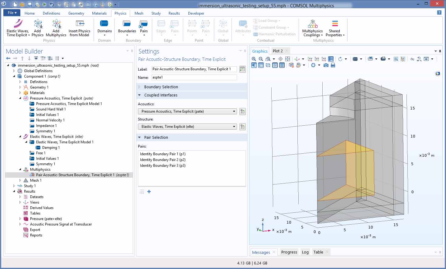
- Immersion Ultrasonic Testing Setup (new model)
Multiphysics for Acoustic-Structure Interaction with the Time Explicit Interfaces
For large transient acoustic-structure interaction simulations, a new Acoustic-Structure Interaction, Time Explicit multiphysics coupling is available. This coupling connects the Pressure Acoustics, Time Explicit and new Elastic Waves, Time Explicit physics interfaces. To take full advantage of the time explicit formulation, the use of nonconforming meshes is essential when coupling domains with different properties. This is achieved through the new Pair Acoustic-Structure Boundary, Time Explicit multiphysics coupling that handles geometric assemblies. The use of nonconforming meshes is a natural extension and use of the properties of the discontinuous elements. You can see this functionality used in the Immersion Ultrasonic Testing Setup model.
New Tutorial Models
Version 5.5 brings several new tutorial models.
Stress Analysis of a Portal Crane
Application Library Title:
portal_crane
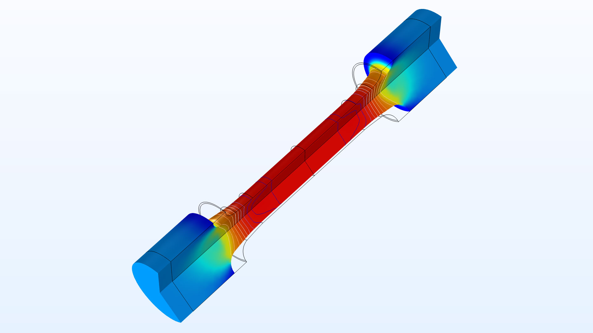
Tensile Test with Strain-Rate-Dependent Plasticity
Application Library Title:
strain_rate_dependent_plasticity
Bimetallic Strip in Airflow
Application Library Title:
bimetallic_strip_fsi
Two-Phase Flow with Fluid-Structure Interaction
Application Library Title:
twophase_flow_fsi
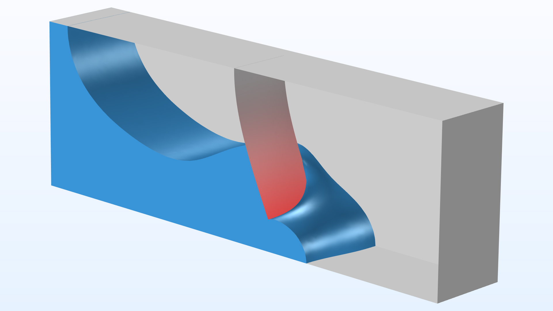
Block Pressing on Arch
Application Library Title:
block_on_arch
Coupled Analysis of Flow and Stress in a Pipe
Application Library Title:
pipe_flow_stress
Instability of Two Contacting Arches

Application Library Title:
two_arches
Random Vibration Analysis of a Deep Beam
Application Library Title:
random_vibration_deep_beam
Bracket — Random Vibration Analysis
Application Library Title:
bracket_random_vibration
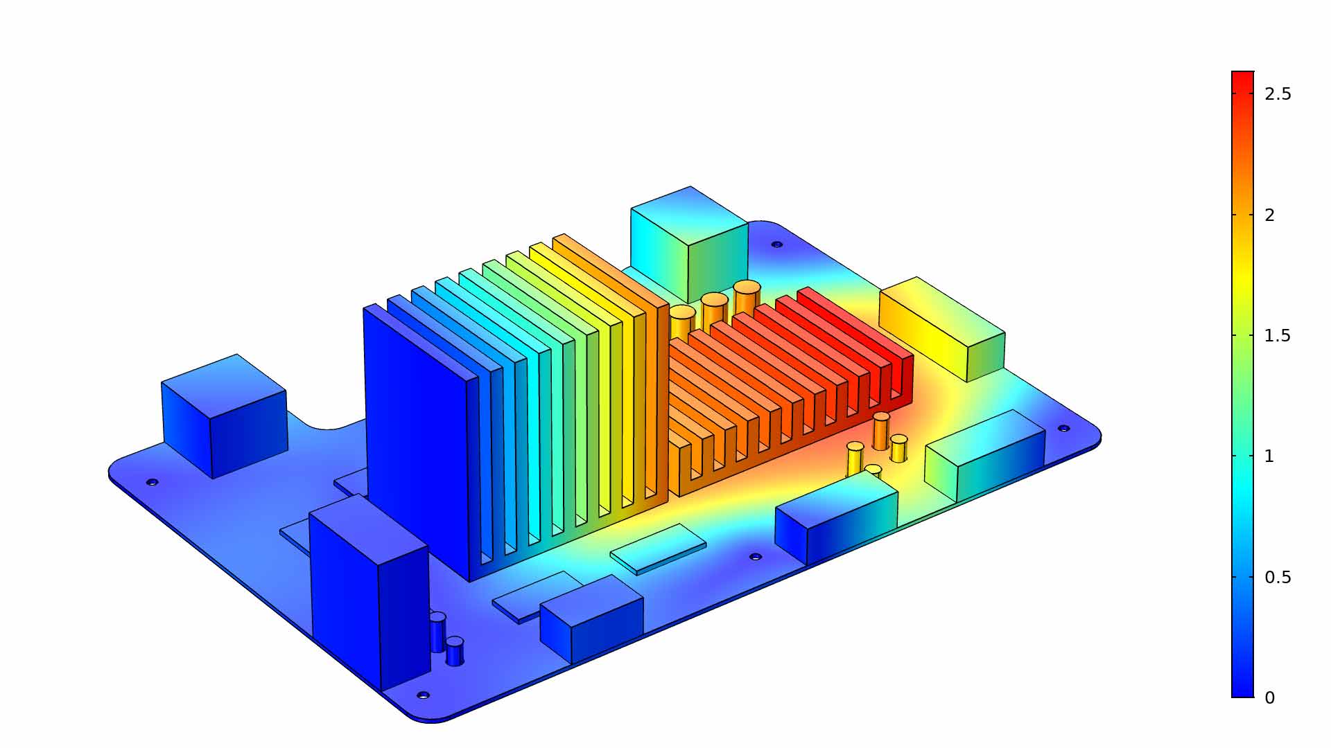
Random Vibration of a Motherboard
Application Library Title:
motherboard_random_vibration
Eigenmodes of a Viscoelastic Structural Damper
Application Library Title:
viscoelastic_damper_eigenmodes
Twisting and Bending of a Metal Frame
Application Library Title:
frame_with_cutout_plasticity
Pressurized Orthotropic Container — Shell Version

Application Library Title:
orthotropic_container_shell
Sensitivity Analysis of a Truss Tower
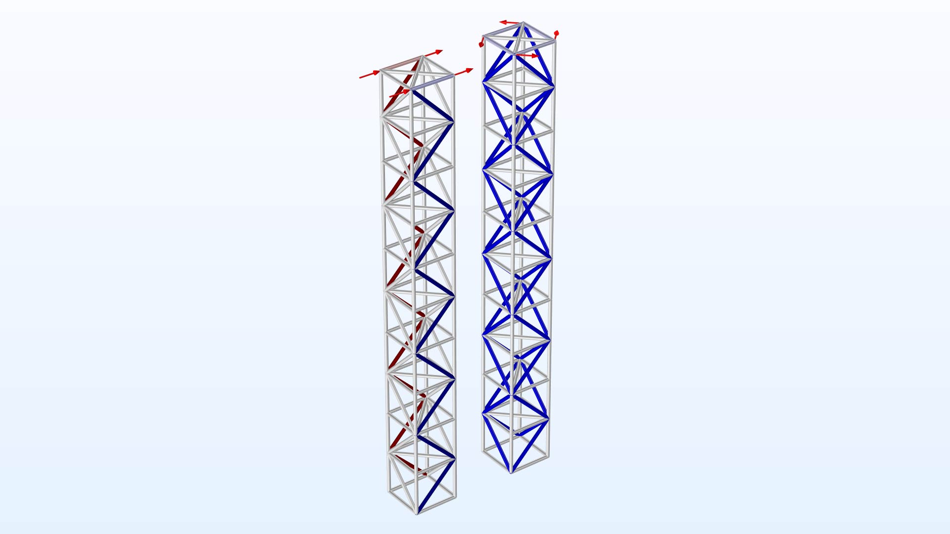
Application Library Title:
tower_sensitivity
Bracket — Topology Optimization
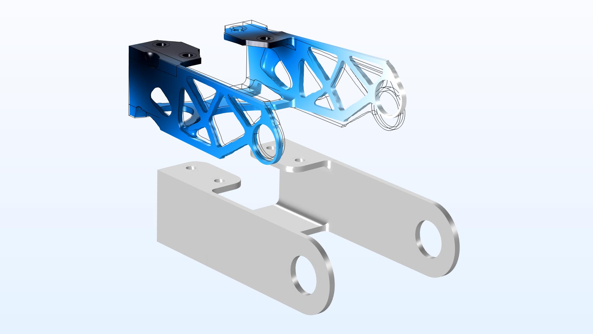
Application Library Title:
bracket_topology_optimization_stl
Isotropic-Anisotropic Sample: Elastic Wave Propagation
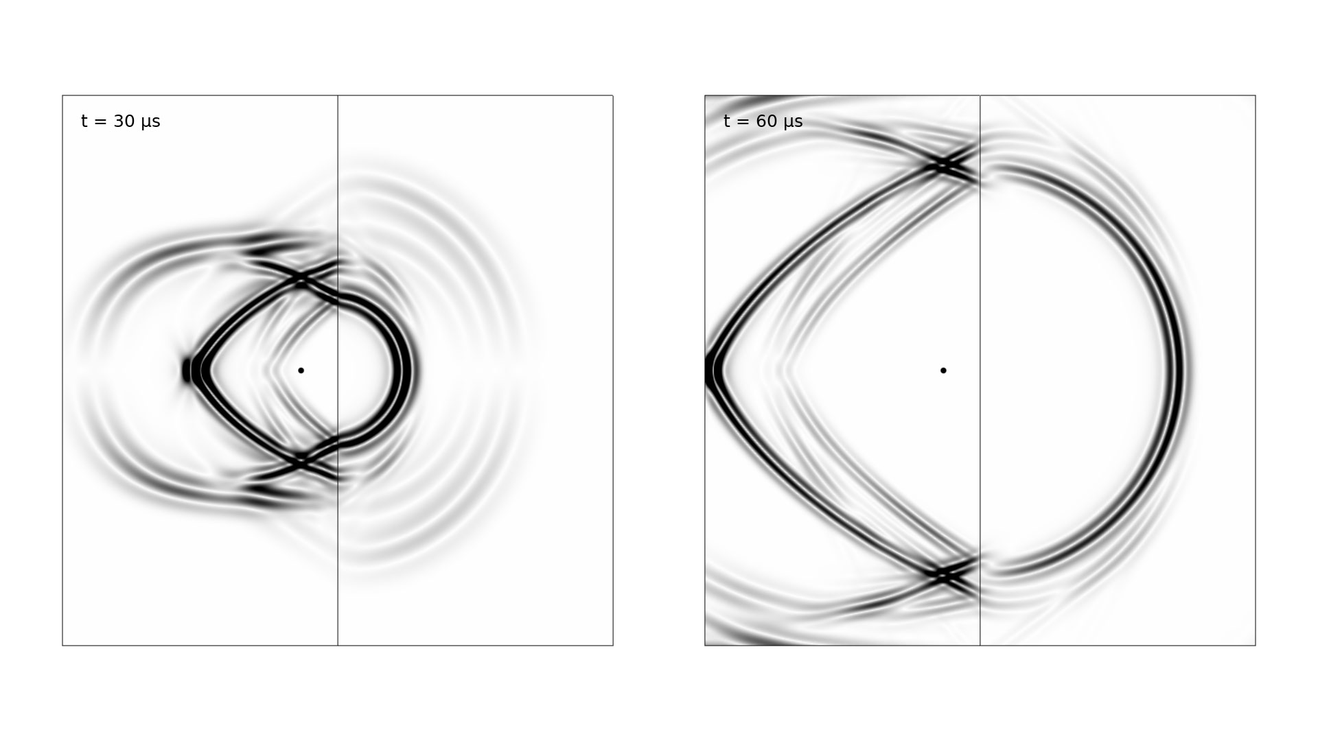
Application Library Title:
isotropic_anisotropic_sample
Ground Motion After Seismic Event: Scattering off a Small Mountain
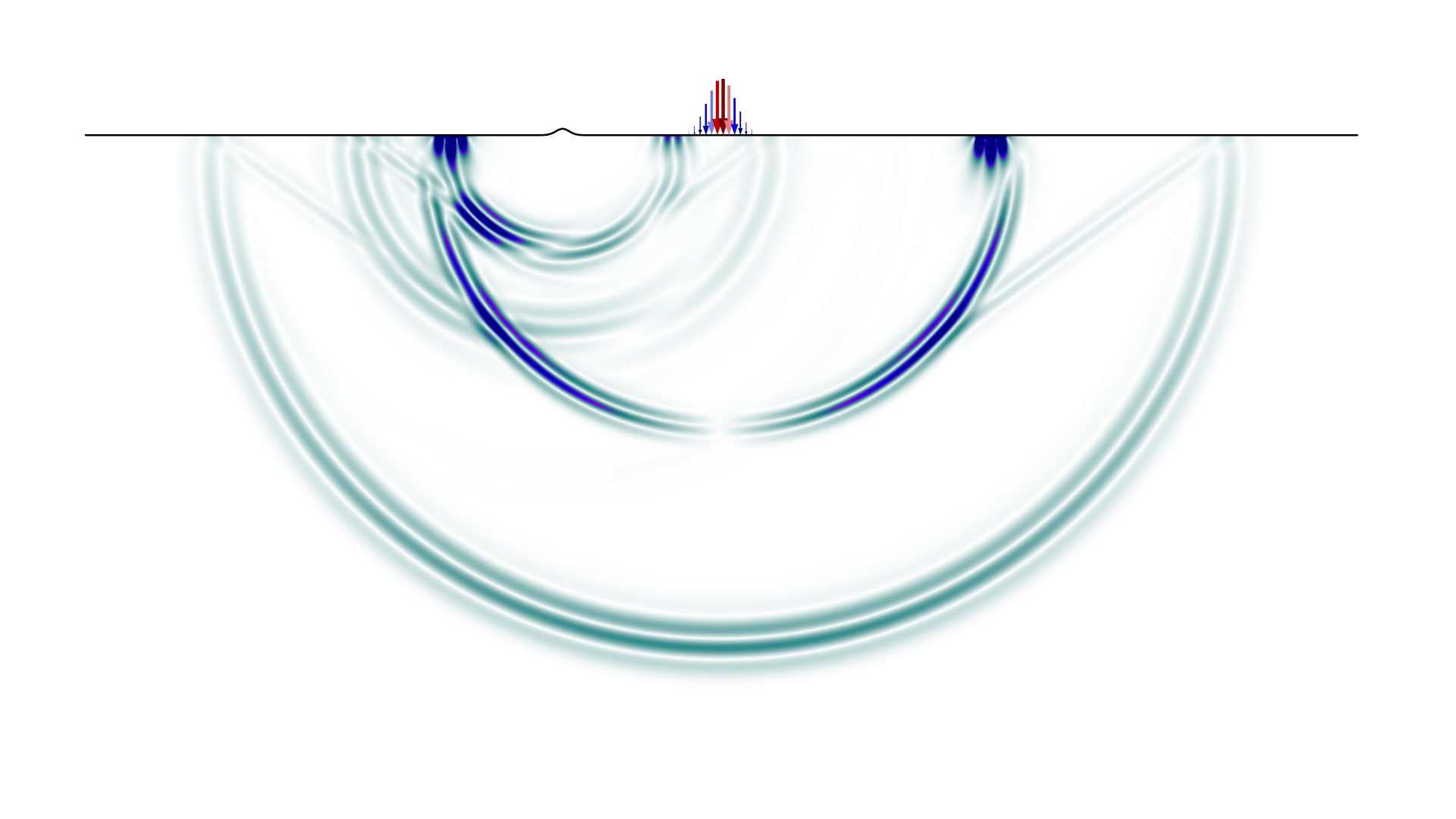
Application Library Title:
ground_motion_seismic_event