Wave Optics Module Updates
For users of the Wave Optics Module, COMSOL Multiphysics® version 5.5 brings coupled full-wave and ray optics simulations, new Gaussian beam boundary conditions, and new variables for periodic ports. Learn more about the Wave Optics Module updates in more detail below.
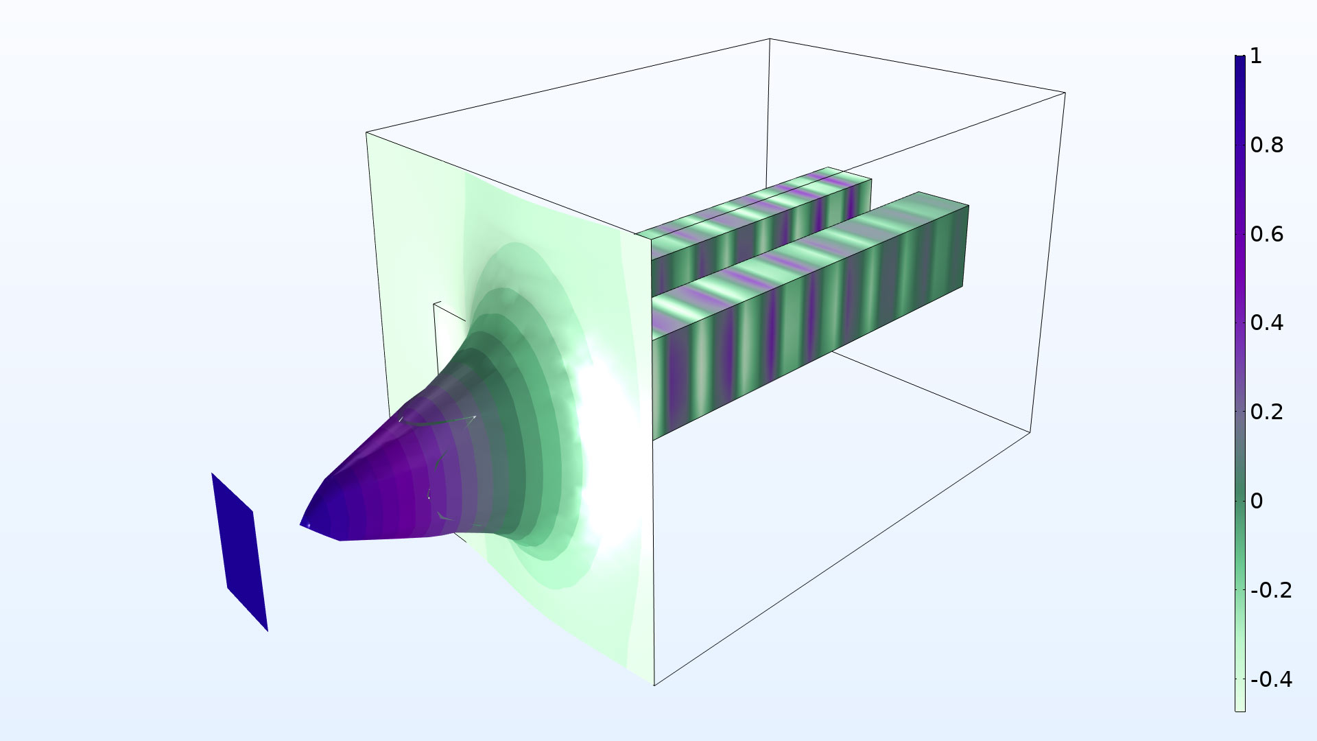
Full-Wave and Ray Optics Simulation Coupling
You can now run simultaneous full-wave and ray tracing simulations by combining the Ray Optics Module functionality with your Wave Optics Module simulations. This enables multiscale electromagnetic modeling, such as analyzing a waveguide beaming into a large room, where a full-wave simulation would be computationally prohibitive. To facilitate this coupling, two new features Release from Electric Field and Release from Far-Field Radiation Pattern have been added to the Geometrical Optics interface in the Ray Optics Module that release rays based on either a near or far field from a full-wave simulation. You can see these new features demonstrated in the Ray Release Based on a Plane Electromagnetic Wave model.

Gaussian Beam Input Option for Scattering and Matched Boundary Conditions
The Scattering and Matched boundary conditions have a new option for the Incident field combo box. Choosing the Gaussian beam option allows for propagation of a Gaussian beam in an arbitrary direction. The Gaussian beam is defined from the paraxial Gaussian beam formula. You can see this new functionality in the Beam Splitter model.
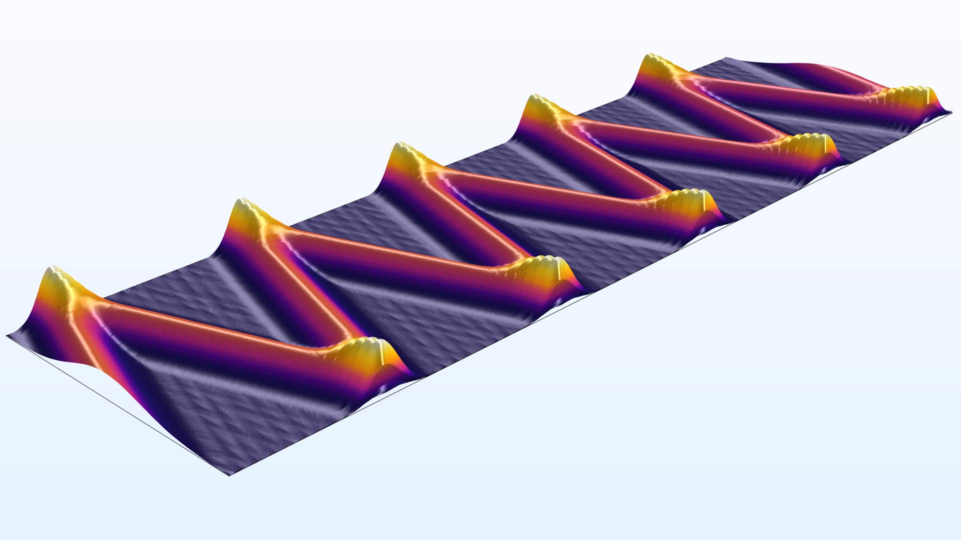
Polarization Plots and Jones Vector Variables
Periodic ports now create a Polarization plot by default. The Polarization plot depicts the polarization state for the different diffraction orders and is based on new postprocessing variables for Jones vector elements. Also, the base vectors, used for defining the Jones vectors, are available for plotting and evaluation. You can see this new functionality in the Hexagonal Grating and Fresnel Equations models.

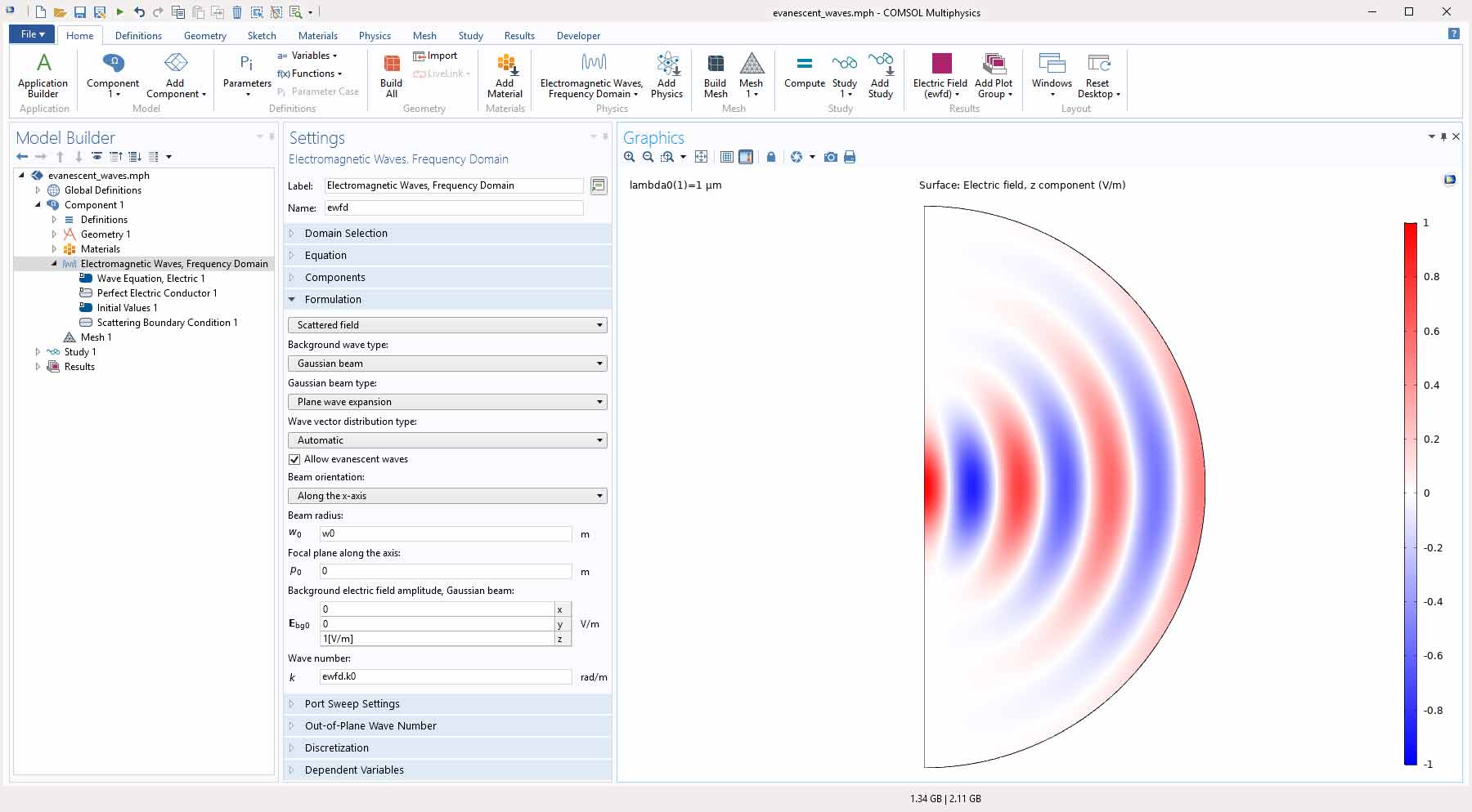
Evanescent Waves for Gaussian Beam Background Fields
When using the Plane wave expansion option for defining a Gaussian beam background field, evanescent waves can now be included in the expansion by selecting an Allow evanescent waves check box. This option can be useful when simulating a tightly focused Gaussian beam, where the spot radius is smaller than the wavelength, propagating away from the focus.
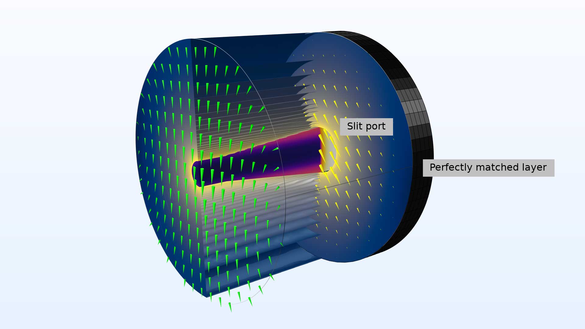
Slit Ports for the Beam Envelopes Interface
Slit ports are now also available for the Unidirectional formulation for the Electromagnetic Waves, Beam Envelopes interface. Slit ports can be useful if several modes are propagating, but only the reflectance or transmittance of one of the modes is of interest. You can use a domain-backed slit port for the mode of interest and let the rest of the modes be absorbed by a Perfectly Matched Layer (PML) in the domain behind the port.
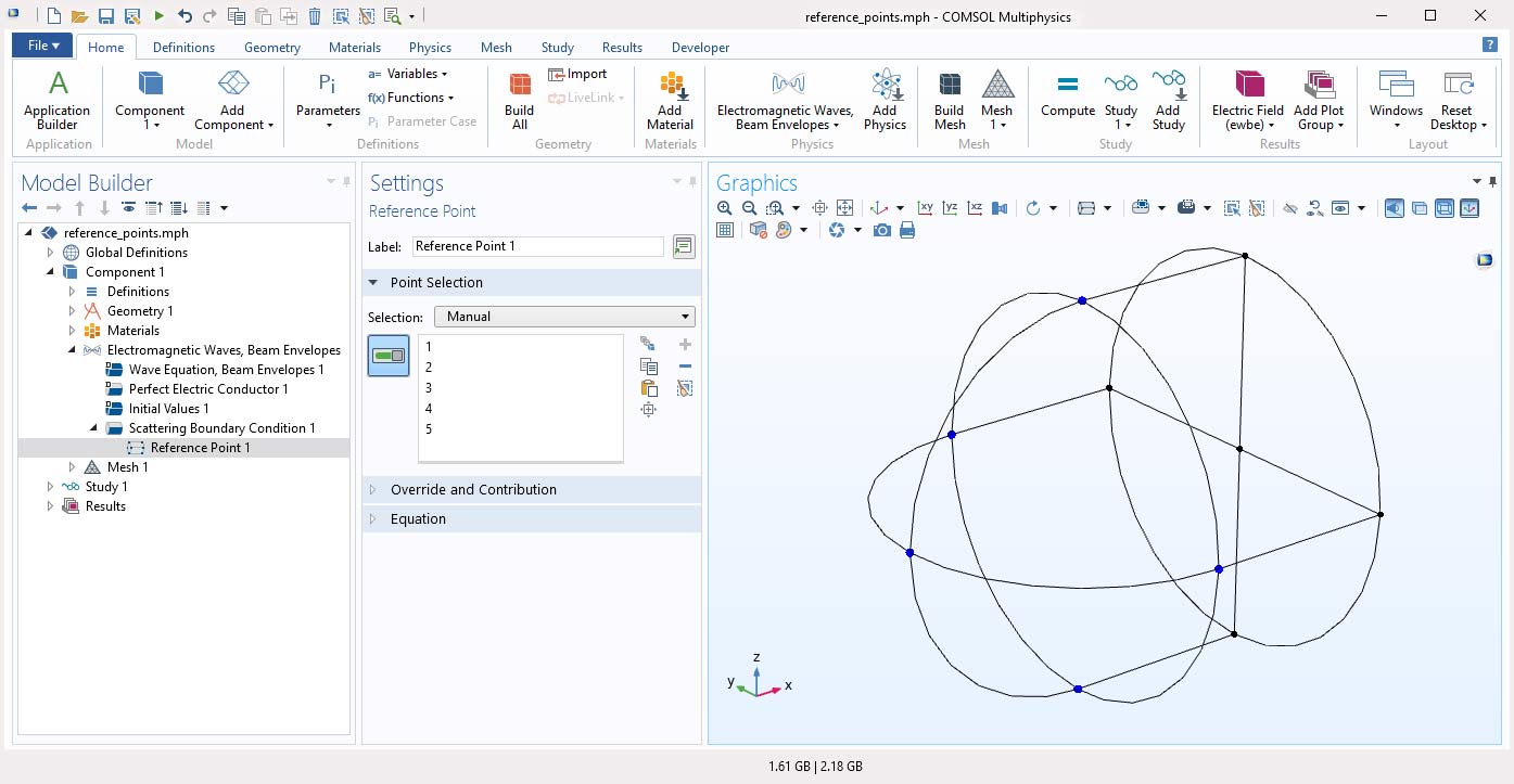
Reference Points for Scattering and Matched Boundary Conditions
The Reference Point attribute is now available for the Scattering Boundary Condition and Matched Boundary Condition for the Electromagnetic Waves, Frequency Domain and Electromagnetic Waves, Beam Envelopes interfaces, when an input field is active. The reference position is defined as the average position of the selected points. This feature is mainly useful when the domain material includes absorption or gain.
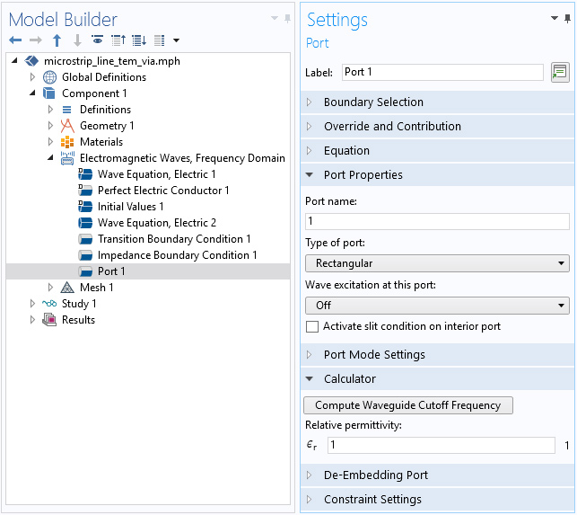
Port Utility
When designing a circuit with an arbitrarily sized feed structure, the cutoff frequency in a waveguide is often overlooked. As a result, the unwanted frequency may accidentally be part of the simulation resulting in unnecessarily long solution times. You can now calculate and remove those frequencies from the simulation. For the Port feature, when using a rectangular or circular port, you can compute the waveguide cutoff frequency based on a user-defined relative permeability.
New and Updated Tutorial Models
Version 5.5 brings several new and updated tutorial models.
Total Internal Reflection
Application Library Title:
total_internal_reflection
Orbital Angular Momentum Beam

Application Library Title:
orbital_angular_momentum
Frequency-Selective Surface, Periodic Complementary Split Ring Resonator
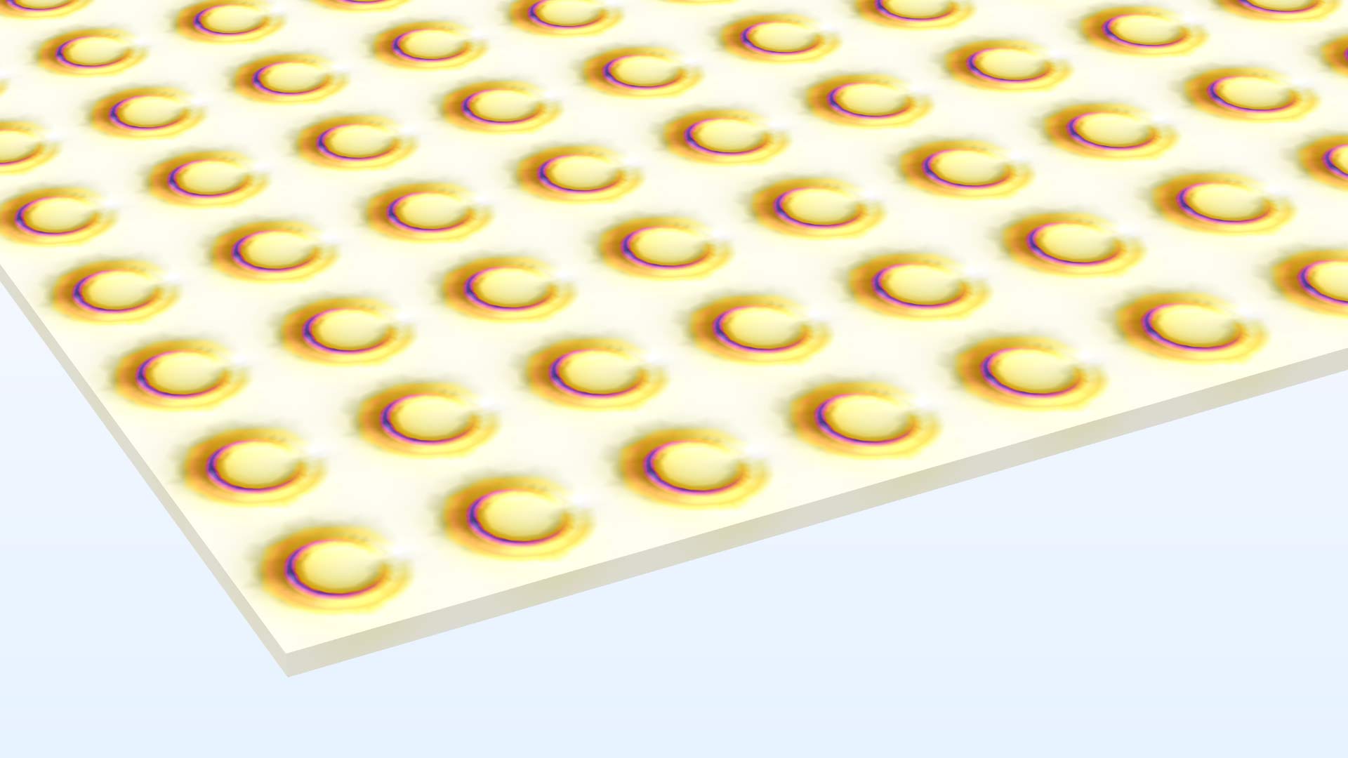
Application Library Title:
frequency_selective_surface_csrr
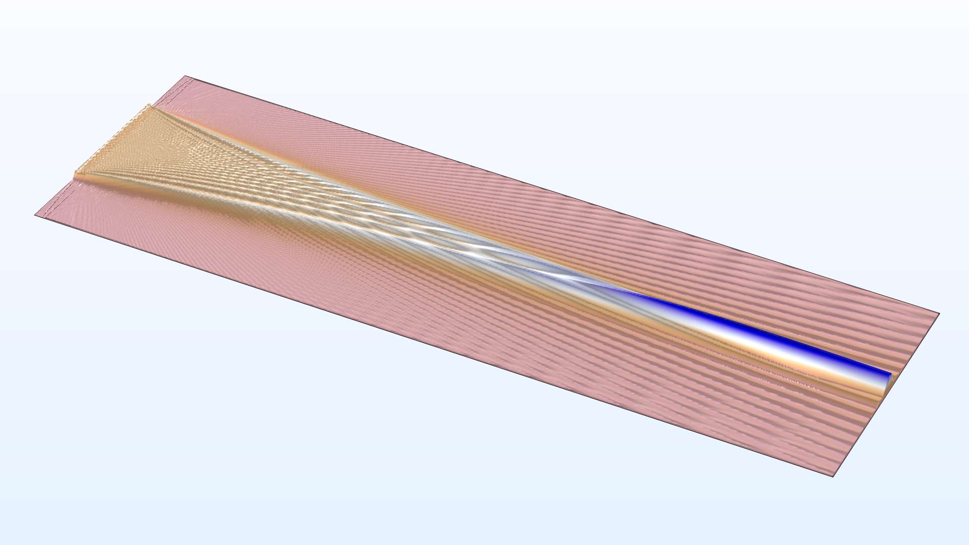
Directional Coupler
Application Library Title:
directional_coupler
Focusing Lens
Application Library Title:
focusing_lens