Design Module Updates
For users of the Design Module, COMSOL Multiphysics® version 5.5 includes a set of new sketching tools used for adding constraints and dimensions to planar drawings for 2D models, 3D work planes, and in geometry parts. The new tools for constraints and dimensions can be used together with model parameters in COMSOL Multiphysics® to drive the simulation, whether for a single run, parametric sweep, or parametric optimization. With these new tools, you are able to create real-world parts more efficiently.
Sketch Tools
The new sketch tools in version 5.5 are included in the COMSOL Multiphysics® license, and more detailed information can be found on the Geometry page. Using the new tools, you can quickly draw a geometry that resembles a desired shape, and then by adding constraints and dimensions, you can obtain the final, desired geometry.
The new sketch tools make it easy to draw a rough geometry quickly.
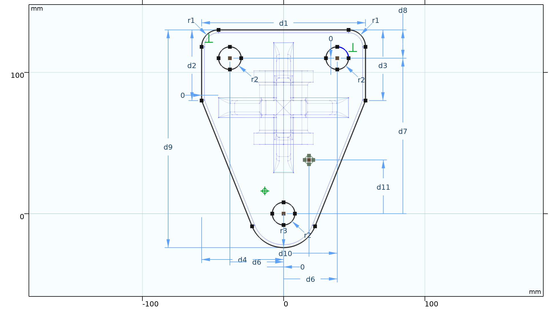
Constraints and Dimensions
A constraint is a requirement on geometric entities that does not have a value, for example, that two edges should be perpendicular or that a line should be tangent to a curve. A dimension (or constraining dimension) is a requirement on geometric entities with an associated value, such as the distance between two vertices, the radius of a fillet, or a coordinate position, for example. You can also define a dimension using an expression that includes parameters, for example, A*5[m] where A is a global parameter.
When applying the constraint and dimension features, the software immediately adjusts the drawing to satisfy the applied feature. To do this, the values of the geometric feature's input fields are adjusted accordingly. Each constraint and dimension is visualized with symbols and arrows in the Graphics window and has a corresponding node in the Model Builder window. You can also choose to enable or disable the use of constraints and dimensions in the Settings window for the Geometry or Plane Geometry nodes.
To apply a constraint or dimension, you can either select them individually or click the Constraint or Dimension buttons in the Sketch tab (also called Smart Constraint and Smart Dimension, respectively) to have the software choose the constraint or dimension based on the entities selected. For example, to set a length dimension on an edge, you could click the Dimension button, click the line, and then drag the mouse to place the dimension arrows and label. To set an angular dimension, you would click the Dimension button, click two lines, and drag the mouse to place the dimension arrows and label. Constraints and dimensions can be applied to several different geometry objects including the output of features such as the Union operation.
Constraints and dimensions are added to a sketch to create an accurate representation of the part.
A drawing that you have created with the constraints and dimensions tools can be in one of several states, including:
- Underdefined
- There are too few constraints and dimensions to define the geometry uniquely. Add more constraints and dimensions.
- Well defined
- The constraints and dimensions define the geometry uniquely and they do not contradict each other.
- Overdefined
- There are too many dimensions. Remove dimensions to get a well-defined geometry.
The state of the drawing will not affect whether or not you can perform an analysis or keep working on a model, but is rather used as guidance.
To ensure the drawing is accurate, you can check that the geometry is Well defined.

Associative Geometry Import
The CAD file import functionality now supports associative geometry import to retain physics and other settings on the geometry after the file is reimported due to an updated design. The import reads information in the CAD files to identify the geometric entities in the file. This information is usually available when importing CAD files saved in the native format of the software where it was created.
Reimporting a modified version of this fan geometry preserves the selection of the blade faces.
Selections from Materials, Layers, and Colors
The CAD file import functionality now generates selections based on the material and layer assignments of the geometric objects, when available in the CAD file. Selections are also generated for colors assigned to geometric entities. The selections are listed in the Settings window of the Import feature.
Use material selections generated during import to easily assign materials to the imported geometry. The selections are also kept when a modified version of the geometry is reimported.
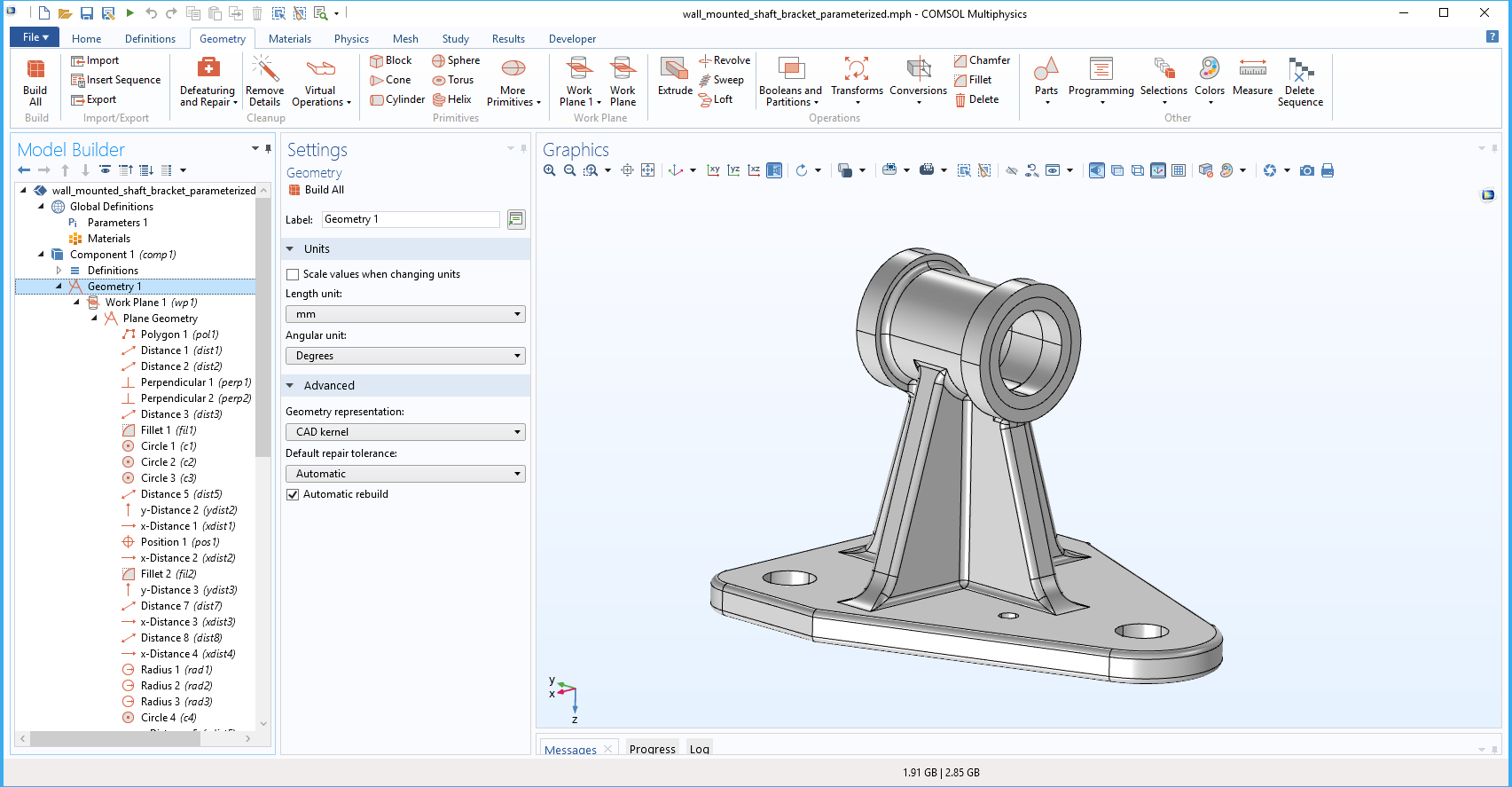
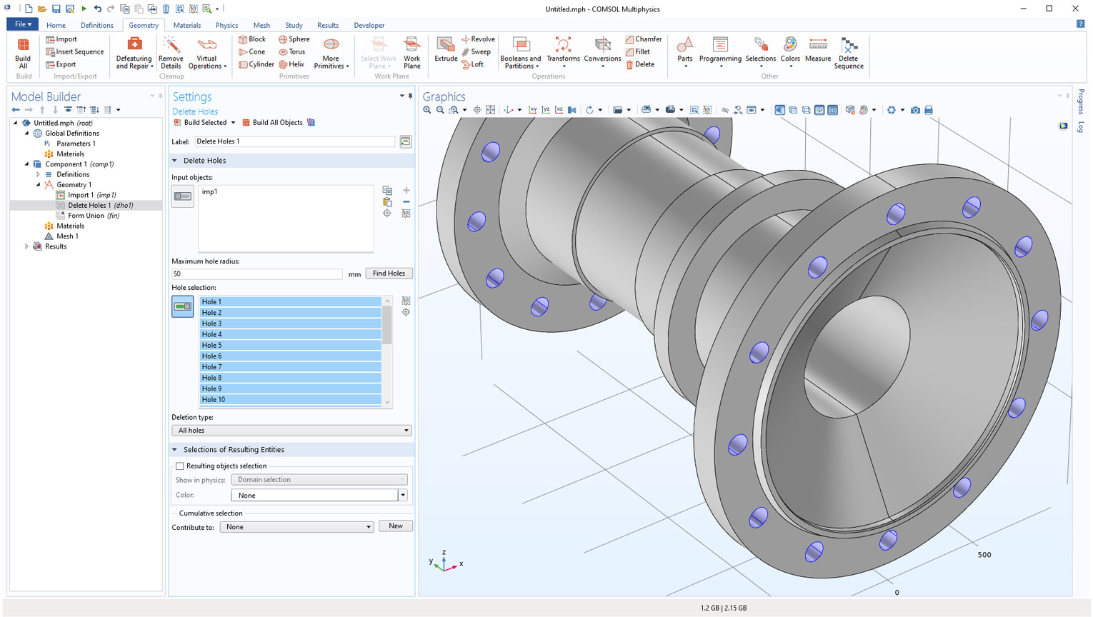
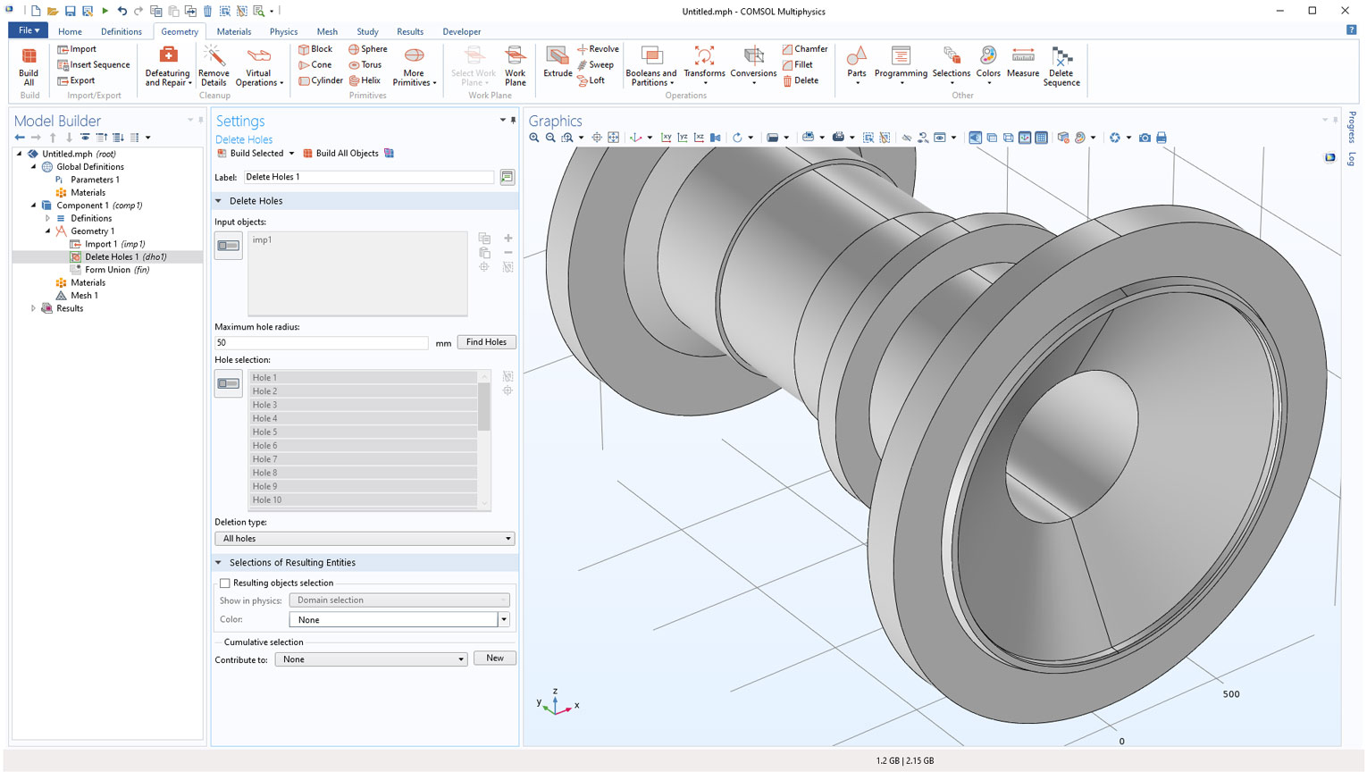
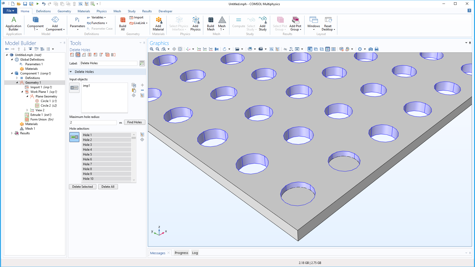
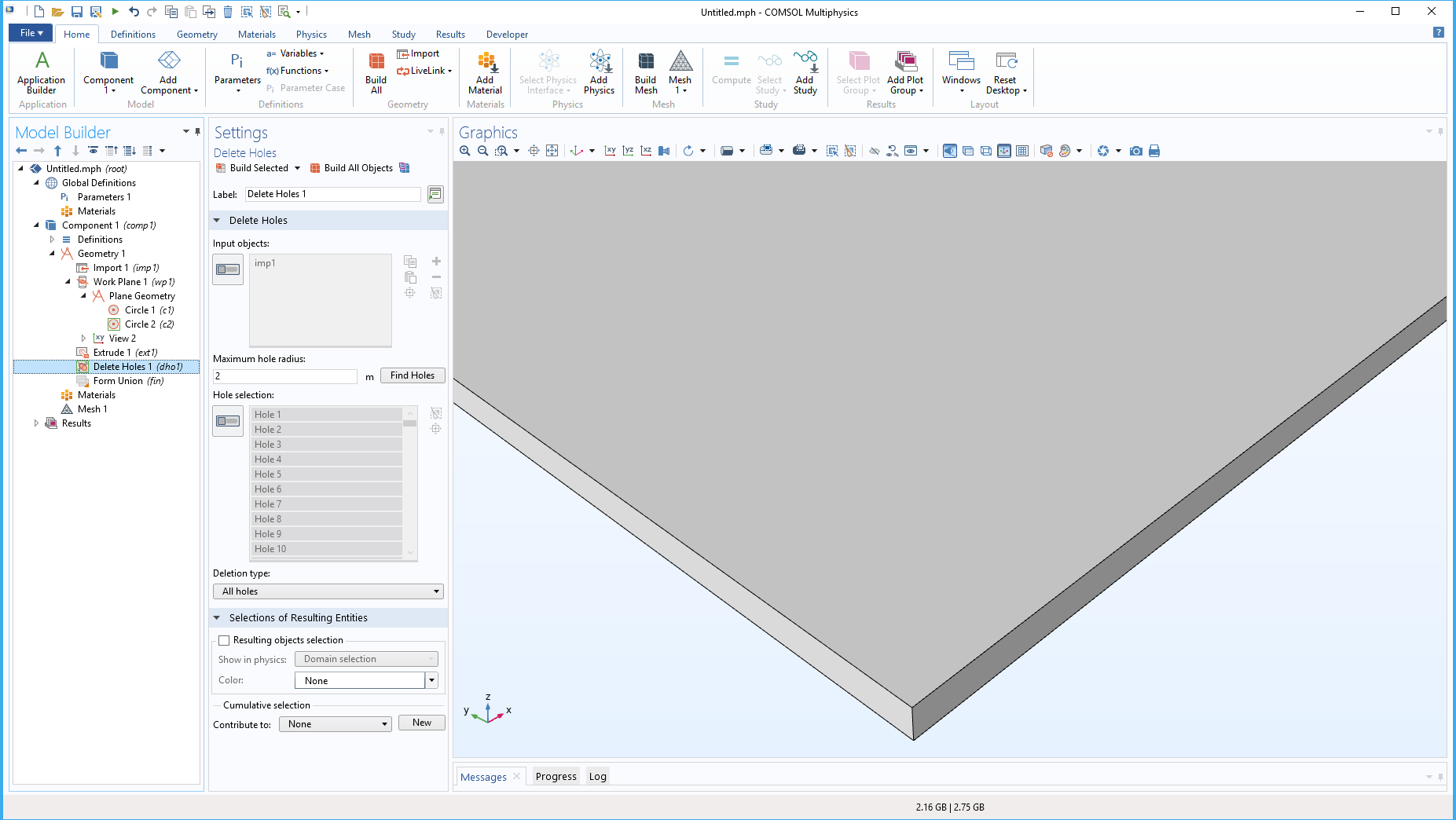
Delete Holes Defeaturing Operation
A new defeaturing operation called Delete Holes finds and deletes cylindrical holes whose radii are smaller than a given number that you can specify. After specifying a maximum radius, a Find Holes button will automatically add the appropriate holes to the selection list.
Support for New and Updated CAD File Format Versions
The CAD file export functionality now supports writing 3D geometry to the following file formats:
- IGES (.igs, .iges): 5.3
- STEP (.step): AP203
The CAD file import and export functionality has been extended to support new versions for the following file formats:
Read from File
- ACIS® (.sat, .sab, .asat, .asab): 2019 1.0
- NX™ (.prt): 1847
- Parasolid® (.x_t, .xmt_txt, .x_b, .xmt_bin): V32.0
- PTC Creo Parametric™ (.prt, .asm): 6.0
- SOLIDWORKS® (.sldprt, .sldasm): 2019
Write to File
- Parasolid® (.x_t, .xmt_txt, .x_b, .xmt_bin): V32.0